NEED:-
The need for this project aroused when once I was trying to interface uart and multiplexed ssds together. The problem was that I had to do 2 process simultaneously that is receive characters from uart send them back to uart, print them at the same time update all ssds. Now ssds use persistent of vision that is a particular ssd is turned on digit is displayed on it then after few microseconds other ssd is turned on and corresponding digit is displayed and this goes on for other ssds also. So to this a mechanism had to be developed that after few us turns on a ssd displays digit, then after few us turns other ssd on displays corresponding digit and at the same time receive digits from uart put them back and displays on term. And apart from displaying on term also update digits to be displayed on ssds.

Fig. 1: Overview of Parallel Processing on ARM 7
SOLUTION:-
To do this firstin arm7 timer 0 is selected as fast interrupt request (fiq) so that after every 1ms it generates interrupt and executes its isr. In the isr one of ssds of multiplexed ssd (ssd1) is turned on and corresponding number (dig1) is displayed then after 1ms again isr is executed and other ssd (ssd2) is turned on and other number (dig2) is displayed and the same process goes on. Initially dig1, dig2, dig3, dig4 have 0 values so all ssds show 0. Now In the while one arm waits for 4 digits if 4 digits are entered at term and terminated by a and received by arm then it displays on LCD, sends back to term and updatesdig1, dig2, dig3, dig4 so digits to be displayed on ssds are updated. If digits entered is not equal to 4 then error is displayed on LCD, term and errr on ssds.
MULTIPLEXED SSD DISPLAY AND POV:-
Basically it consists of four ssds having common a, b, c, d, e, f, g, h and one enable as shown in figure. The principle used is PERSISTENCE OF VISION (POV).Persistent of vision is the phenomenon by which an afterimage is thought to persist for approximately 1/25 of second on retina. So to obtain continuity first an image is displayed then before 1/25 of second another image is displayed so we human see it as continuous one. Same as in video camera shows images one by one at certain rate (<1/25 of second) one over the other so that we see it as continuous one. In order to do this first one of the ssd is turned on then corresponding to number to be displayed pattern is generated by turning some bits on and off of a, b, c, d, e, f, g and h. Then after few ms (I have taken 1ms) other ssd is turned on and corresponding to number to be displayed some bits of a, b, c, d, e, f, g, h are turned on and off. Then same process is continued for other 2 ssds also. So if after every 1ms delay ssds are turned on then if a particular ssd is turned on and a digit displayed it would take 4ms for it to turn on again and that is (4/1000 of second) so we would see it as a continuous image. This principle can be used in a number of phenomena like task scheduling, parallel processing etc.
h = DP

Fig. 2: Representational Image of Multiplexed SSD Display with Pin Descriptions
ARM 7 TIMER 0 AS FIQ
(Code explanation)
ARM 7 has 32 sources of interrupts and it has 3 types of interrupts (fiq, vectored irq and non-vectored irq) in this project timer 0 is declared as fiq. Fiq as the name suggests is fast interrupt request and has the first priority that is if we have many interrupts and if more than one interrupt (i.e. it’s isr) needs to be served then isr of fiq will be served first followed by vectored irq then non vectored irq and for the same reason fiq is used for task scheduling.
In this project as said timer 0 is declared as fiq and its isr is executed after every 1ms. I took 4 variables dig1, dig2, dig3, dig4 and assigned them = 0 globally. Ssds enable are active low and connected to P0.10, P0.11, P0.12, P0.13 so In the isr first one of the ssd (eg ssd1) is turned on by sending 0 to P0.10 as active low enable and then corresponding to dig1 i/o pins which are connected to a, b, c, d, e, f, g, h of ssds are turned on and off note these are also active low. I/O pins connected to ssd digit showing part are:-
a = P0.2
b = P0.23
c = P0.15
d = P0.14
e = P0.6
f = P0.7
g = P0.8
h = P0.9
Understanding Coding
Then after 1ms again isr is executed and other ssd (eg ssd2) is turned on by sending 0 through other i/o pin P0.11 connected to other ssd’s enable and corresponding to dig2 i/o pins connected to a, b, c, d, e, f, g, h of ssds are turned on and off. And the same process continues. For other ssds also. Initially dig1, dig2, dig3, dig4 = 0 so each ssd shows a 0.

Fig. 3: Screenshot of Virtual Terminal
In isr first a variable is statically declared=0 then there are four conditions comparing count to 0,1,2 and 3 so as isr is executed first count is incremented then compared if it equals 0 then ssd1 is turned on and a function ssd_display (dig1) is called which displays dig 1 on ssd then again when isr is executed count is incremented if it == 1 then ssd2 turned on and corresponding digit displayed using ssd_display (dig2) same process is continued for others but when count==3 ssd4 is turned on and digit displayed using ssd_display (dig4) and count made to 0. So as count=0 so again same process goes on from ssd1.
In while(1) first arm7 sends the string “enter 4 digit number“to be printed on vterm, done using function uart0_putstrn (““) then waits to receive (this can also be based interrupt based) 4 digit number for this I used an array digit [], the function uarto_getch () and a while loop.First of all I took a variable I (i) assigned digit [0]=0 incremented I(i) then saved the received char in digit[i] this is done till digit[i]!=’a’ so this continues till ‘a’ is sent from term so after the entering the number at terminal to send we press a and this is done using while loop condition while (digit[i]!=’a’)
We see that if a 4 digit number is entered then I is incremented 5 times so to check if number is a 4 digit or not I used the if condition. if i==5 then the number is of 4 digit otherwise not. Now if number! =4 digit number then ‘error’ is sent back to terminal using uart0_putstrn (), displayed on LCD using lcd_strn() and dig1=10, dig2=11, dig3=11, dig4=11 are updated corresponding to these value errr is displayed on ssd (this can be seen in function ssd_display). If number==4 digit number then the number is sent back to terminal, displayed on LCD and
dig1=digit[1]-48;
dig2=digit[2]-48;
dig3=digit[3]-48;
dig4=digit[4]-48;
are updated. This is done as uart_getch returns char so the array digit [] is of char type but ssd_display takes int value so this is basically char to int conversion. So like this the process goes on.
Now I also used important function ssd_display ( int ) it takes numbers from 0-9 and corresponding to the number turns on and off a, b, c, d, e, f, g, h of ssds by turning on and off respective i/o s.
Note in this project we have just one interrupt so fiq doesn’t matter much but if we have many fiq, irq then it matters.
This can’t be done sequentially.
U can also do many processes like this. (Task scheduler)
IMPORTANT INFORMATION
-IDE used KEILUVISION 4
– SIMULATED on PROTEUS 7.1
– BOARD used LPC2148
– Codes provided
– vterm_num_print
– Hex files provided
– vterm_num_print.hex
– Some additional .h and .c are also provided like delay, uart0, timerfiq etc.
– Proteus .dsn is also provided vterm.dsn.
All these are in their respective folders i.e:-
-vterm_num_print
-proteus_vterm
-Build schematic on proteus load the provided hex files in respective lpc2148 then run to see output.
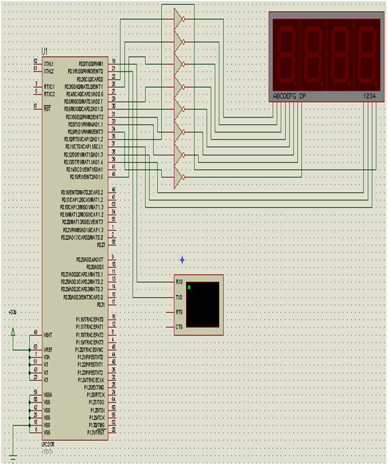
Circuit Images

Fig. 4: Prototype of LPC2138 Interfacing with Multiplexed SSD Display

Fig. 5: Image showing numbers displayed on SSD Display successfully from LPC2138

Fig. 6: Image showing numbers displayed on SSD Display incorrectly from LPC2138
Circuit Diagrams
Project Video
Filed Under: Electronic Projects
Filed Under: Electronic Projects

Questions related to this article?
👉Ask and discuss on Electro-Tech-Online.com and EDAboard.com forums.
Tell Us What You Think!!
You must be logged in to post a comment.