Children often get involved in watching cartoons, movies and their favourite TV show. Hence they fail to pay attention on their studies even at the time of examination.
• So to keep an eye on children, we have designed a parental control device.
• When the children in your home hold the remote of the television towards the TV and press any button then a loud sound would be generated by the device. This will let you know that your child has tried to switch on the TV.

Fig. 1: Prototype of 555 IC based TV Parental Control Device
• The main advantage of this circuit is that you can easily do your work without any trouble as it produces loud noise so you can hear the noise while working in the kitchen or while sitting in the nearby room.
• So your children will not watch the TV at the cost of their studies.
• All you need to do is just place the circuit near your TV.
• You can also use this circuit on AC remote that works on 38Khz frequency.
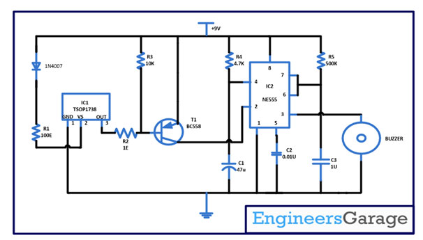
In the parental control we are connecting TSOP 1738 which works like a sensor. It helps to detect the interference coming from the nearby surrounding. TSOP1738 works on 38Khz of frequency and filters out all the rest IR rays. Most of the remotes work on 38KHz frequency, so whenever your child presses the button of remote you will hear the sound.
We have made pin 1 of the TSOP to grounded and input signal is applied at pin 2 while output is taken out from pin3. Output from the TSOP is applied to base of transistor T1 BC558 which is a PNP transistor. The output from the transistor is given to IC NE555 at pin 2 and output is taken out from pin3. In this circuit NE555 is connected in a monostable state.
Working of this circuit is very simple. When your child presses any button of the remote, TSOP1738 receives IR rays. Then it filters out all the IR rays except 38KHZ which is normally produced by the TV remote. After that these IR signal is passed on to IC NE555 at pin 2 through a transistor BC558. During this time voltage at pin 2 is at low state due to which output at pin 3 turns high and sound from buzzer can be heard.
When your TV is switched off or any of the buttons of remote is not pressed pin 2 of NE555 remains at high state and output from pin 3 is at low state. As a result no beep sound comes out from the buzzer.
Diode is used in the circuit to provide correct power supply for the proper working of TSOP. As excess voltage may destroy the sensor, Capacitor C2 connected at pin 5 of NE555 is used to reduce the noise. The circuit is operated at a power of 9V.
Another application of this circuit may be that it can be used like a calling bell to call peon in offices. As you do not require extra circuitry, you can use AC remote or TV remote as transmitter and this circuit as receiver. Further, it can be applied to several other circuits based on your necessity and creativity.
Circuit Diagrams
Filed Under: 555 Timers, Electronic Projects


Questions related to this article?
👉Ask and discuss on EDAboard.com and Electro-Tech-Online.com forums.
Tell Us What You Think!!
You must be logged in to post a comment.