PC temperature controller will give an alarm when your PC overheats. This will prevent the damage of expensive components. Today's computer have inbuilt fan and also consume less power because of use of LSI and VLSI technology. But sometimes it happen fan stop cooling due to any reason and unable to dissipate heat. We do not come to know this and the microprocessor or motherboard inside the PC get over heated or damage. This in turn led to failure of devices or your PC. So solve this problem you can use this simple circuit which will give you alarm when your PC over heat. You can also install this small unit inside your PC.
[[wysiwyg_imageupload:10527:]]
Fig. 1: Prototype of PC Temperature Controller Circuit on Breadboard
This circuit is based on three IC namely CA3130, E555 and LM35 which work as a sensor to detect the amount of heat present with few more components.
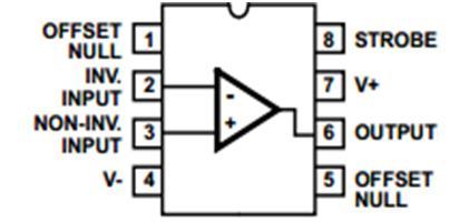
IC CA3130 is a operational amplifier which combine the advantage of both CMOS and bipolar transistor on a single chip. Operating voltage range varies from 5V to 16V. CA3130 has a advantage that they can be phase compensated with a single external capacitor and have terminals for adjustment of offset voltage. In this you can adjust the reference voltage at inverting and non inverting pin so that when voltage at inverting pin is more than non-inverting pin it will make the out pin high and vice versa. Pin configuration of CA3130 IC is shown below.

Fig. 2: Pin Configuration of CA3130 IC
And LM35 is a precision integrated circuit temperature and its output voltage is linearly proportional to centigrade temperature. LM35 detects the surrounding temperature and according to reference value set it will give you the output. When output voltage is multiplied by 100 it will give you the temperature sensed in degrees. So you can easily set your reference voltage. Pin configuration of LM35 IC is shown below.

Fig. 3: Pin Configuration of LM35 IC
In this circuit we have set the fix voltage at inverting pin that is at pin 2 of IC2 and non inverting pin 3 of IC2 is connected with the output pin 2 of IC1 through a resistor. Initially we have to do hit and trial to set the temperature with the help of variable resistor VR1. VR1 provide a reference voltage that can be set anywhere from 0V to approx. 1V.
In our circuit we have set a 0.71V approx at pin 2 which means when temperature reaches above 71 degree Celsius it will give you an indicator with the help of speaker. Now when temperature at IC1 increases because of overheating of components present inside PC voltage at pin 2 IC1 also increases which increase the voltage at pin 3 of IC2 and when voltage become more than 0.71 V it will make the output pin 6 of IC1 high. This high output is provided to pin 4 which reset input pin.
Here 555 timer is working in a-stable mode and high on reset pin will bring the IC3 into conduction making pin 3(output pin) high and speaker connected through it start sounding and when temperature reaches below the set value speaker stop sounding to show that your device is safe.
Circuit Diagrams
Project Components
Project Video
Filed Under: Electronic Projects
Filed Under: Electronic Projects


Questions related to this article?
👉Ask and discuss on Electro-Tech-Online.com and EDAboard.com forums.
Tell Us What You Think!!
You must be logged in to post a comment.