In this porject a circuit is made which can switch on the device when the light falls on it. For this I will use LM358 IC which is operational amplifier. I have made the circuit with LDR and few more components. But when I interchange the LDR with photodiode, phototransistor and transistor (L14F1) my circuit works well without changing any other components. Before understanding the circuit which I have developed, first let’s have a look on the components used in the circuit.
1. IC LM358– LM358 consists of two independent, high gain operational amplifiers in one package. Important feature of this IC is that we do not require independent power supply for working of each comparator for wide range of power supply. LM358 can be used as transducer amplifier, DC gain block etc. It has large dc voltage gain of 100dB. This IC can be operated on wide range of power supply from 3V to 32V for single power supply or from ±1.5V to ±16V for dual power supply and it also support large output voltage swing.
Pin configuration of IC is shown below-
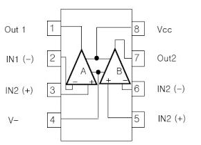
Fig. 1: Pin Configration of IC LM358
From the above figure you can see that operational amplifier has two inputs and one output in one independent LM358. Inputs are at pin 2 (negative pin) and 3 (positive pin), positive pin is used for positive feedback and negative pin is used for negative feedback. In ideal condition when no feedback is applied, gain of the operational amplifier should be infinite. When voltage at pin 2 is more than voltage at pin 3 it will raise the output towards the positive maximum voltage and a slight increase at negative pin compared to positive pin will lower the output towards the negative maximum. This feature of operational amplifier makes it suitable for the purpose of level detection.
2. LDR– LDR is a device whose sensitivity depends upon the intensity of light falling on it. The resistance of LDR decreases when intensity of light falling on it increases and vice versa (resistance increases when intensity of light falling on it decreases). In dark or in absence of light, LDR exhibits a resistance in the range of mega ohms, which decreases to few hundred ohms in presence of bright light.
Testing of LDR
You can check LDR with the help of multi-meter. Keep your multi-meter in ohm or resistor measurement region. When you cover the LDR its resistance will be very high and when you place it in light it decreases. This phenomenon indicates LDR is working correctly. We are utilizing this property of LDR to act at your LDR is working correctly. A sensor, since a varying voltage drop can be obtained with varying light.
3. Photodiode– Photodiodes convert light into current or voltage depending on its mode of operation. It is a PN junction or PIN structure. When a photon of sufficient energy strikes the diode it creates a free electron and a hole. Now the holes move towards the anode and electrons towards the cathode and a photocurrent is created.
Testing of Photodiode
You can check it with the help of multi-meter. Place you multi-meter in mV range. Now put the lead of multi-meter on leads of photodiode. Take the reading in dark as well as in presence of light. It shows deflection in reading in light and dark (in dark reading will be more) than your photodiode is working fine.
4. Phototransistor-Phototransistor is a light sensor similar to basic transistor but has transparent cover.Phototransistors provide a much better sensitivity than photodiode. Phototransistor has large base region than collector as compared to another transistor. They are made using diffusion or iron implantation method. Phototransistor works in active region. Generally its base is left open to sense the light falls on it. When light falls on its base it causes the electron hole pair to be generated. This phenomenon mainly occurs in reverse biased base collector junction, because of electric field electron hole pair move and provide the base current, causes electron to be injected into emitter.
Testing of Phototransistor
You can check the phototransistor with the help of multi-meter. Set your multi-meter in resistance measurement region than put leads of multi-meter on collector and emitter. Now cast some light on phototransistor and then remove the light. You can see the deflection in reading of multi-meter in light reading is small in comparison to dark. If this phenomenon is occurring than you can say your phototransistor is good. You can also use transistor L14F1 in place of phototransistor and the process to check is similar how we have checked phototransistor.
It is always a good practice to check components before using it.
Application of circuits
– The circuit which I have made can be used as dark sensor or light sensor with very little modification. Therefore you use it as a security circuits like in intruder alarm, morning alarm, magic eye, luggage alarm or it will on the light in darkness or off the light in morning etc according to your application.
– In the circuit diagram I have used a LED to show the output. You can also use relay in place of LED to connect buzzer or any external component like bulb, door bell etc.
Working of circuit
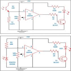
Working of circuits is very simple as we know LM358 compares the voltage applied at input pin and provide you the output. The voltage level which we want to detect is applied on either of the input pins and the voltage to be detected is applied on the other pin. For dark sensor circuits we are applying voltage on negative pin and voltage to be detected is applied on positive pin. Whenever input voltage applied on positive pin because of light which falls on LDR, photodiode and phototransistor slightly rises above the voltage on negative pin the output suddenly raises to the positive maximum and remains positive until the input voltage falls below the level to be detected. Transistor T1 is used to amplify the signals to drive the LED and resistor R1 is used as current limiter to protect LED and for light sensor circuit just reverse of above phenomenon is occurring. You just change the LDR with photodiode and phototransistor and see circuit is working properly and sensitivity of circuit also increases. You can also connect different components and devices at the output, so try connecting your own device and see the output.
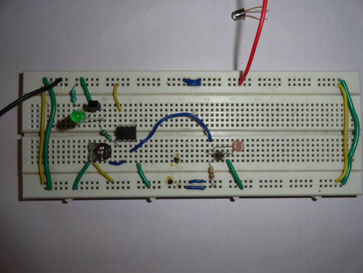
Fig. 2: Prototype for Performing Experiments With LM358 on Breadboard
Circuit Diagrams
Filed Under: Electronic Projects

Questions related to this article?
👉Ask and discuss on Electro-Tech-Online.com and EDAboard.com forums.
Tell Us What You Think!!
You must be logged in to post a comment.