I used Stm32CubeMx code configurator and keil uvision 5 ide for code writing and compilation. If you have no previous experience of Stm32CubeMx and keil ide then i suggest you to first take the getting started tutorial with Stm32CubeMx and keil.
Light detector switch with Stm32 microcontroller and Photoresistor
Stm32f103 Configurator – Stm32CubeMx
Light detector Input/Outputs
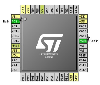
So we need one single gpio(general purpose input/output pin) as input(for light sensor) and one as output(for controlling light bulb). Stm32f103 Port-A Pin#10 is used as input and Port-C Pin#13 is used as output. Stm32f103 used pins are shown below.
Stm32CubeMx Pin Configuration for Light sensor project
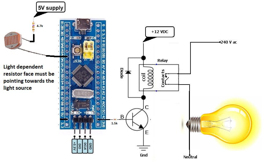
Street Light detector switch – Circuit diagram
Port-A Pin#10 is our output pin. Through output pin i am controlling a transistor. Transistor is used to switch heavy loads. A 12 volt relay is connected to collector pin of transistor. Relay is activated and deactivated by controlling the base of transistor. An AC powered bulb is connected to relay output pins. So now when we switch on or off the transistor we are actually switching the bulb. Diode across the coil of the relay is protecting the circuit from induced and back emf(electro motive force). Note output pin is also internally pull down.
Light detector code
if(HAL_GPIO_ReadPin(LdrPin_GPIO_Port, LdrPin_Pin)==GPIO_PIN_RESET)
Now if light is not falling on the sensor or the intensity of light is not enough to break the reverse barrier of LDR(light dependent resistor) then switch on the bulb. The statement which switches on the bulb is
HAL_GPIO_WritePin(Bulb_GPIO_Port, Bulb_Pin,GPIO_PIN_SET)
else if light is present and falling on the ldr, also lights intensity is enough to forward bias the ldr then switch off the bulb. The statement which switches off the bulb is
HAL_GPIO_WritePin(Bulb_GPIO_Port, Bulb_Pin,GPIO_PIN_RESET)
Future Work:
One can connect the system with internet, cloud and create a log/database of switching on and off the light. Another feature can also be included to switch the bulb remotely through a web connection. Other sensors can also be introduced in the project and a remote corp field can be monitored and autonomously controlled with the system. Such as watering the corps, monitoring temperature, controlling pumps and lights etc.
I made a nice smart garden weather project using a WiFi enabled esp8266 controller. Check out the project below.
Filed Under: Microcontroller Projects, STM32.


Questions related to this article?
👉Ask and discuss on Electro-Tech-Online.com and EDAboard.com forums.
Tell Us What You Think!!
You must be logged in to post a comment.