Using this system, you can remotely monitor the battery level, mains voltage, battery run time, temperature. It designed using PIC16F877A microcontroller for reducing the external components, such as external ADC, OP-AMP, large number of resistors and capacitors. Lesser external components increase the circuit response and stability. And also decrease the power consumption, noise.It is assumed that the reader has gone through the project How to get started with PIC and done all the things discussed in it.
The protection can be done by an easy manner. Temperature and battery dry run protection circuits are inbuilt. So there are no external circuits needed. It is very useful for IT industries, computer laboratories, colleges and schools.
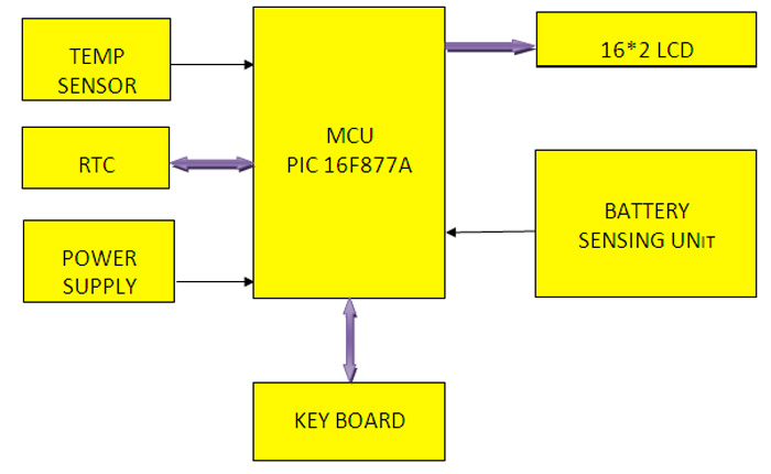
FIG -1
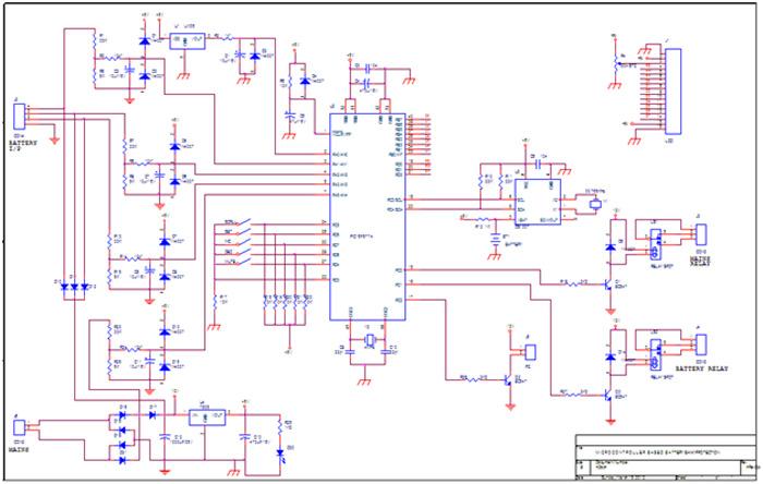
The functional block diagram of microcontroller based battery bank protection is shown in Circuit Diagram tab 2.It consists of 3 sensing blocks, power supply section, key board interfacing, display interfacing with PIC. For This Project Reader Should have Knowledge of How to start with PIC.
Circuit Description
Circuit Description
Microcontroller PIC 18F877A:
PIC 16F877A(shown in fig.2 U2) is a low power, high performance 40 pin PDIP, CMOS 8-bit microcontroller with 8kb flash memory. The important feature of this is it is having a EEPROM Data Memory of 256 bytes. Its other features includes 368 byte of Data Memory, 33 Input Output pins, programmable code protection, 16-bit timer counter with 8-bit prescaler, two 8- bit timer counter with 8-bit prescaler, WDT with its own on-chip RC oscillator for reliable operation and Synchronous I2C port.
Power Supply:
The 230V, 50Hz AC mains is stepped down by a transformer X1 to deliver a secondary output of 12V, 500mA. A bridge rectifier comprising diodes D16,D18,D19&D21, filtered by a capacitor C12 and regulated by IC 7805(U4), rectifies the transformer output. 40mm heat sink is used to dissipate the heat. The anode of diode D17 is connected with the positive terminal of bridge rectifier and its cathode is connected to capacitor C12. The cathode of D17 is connected with the cathodes of D10, D11 and D12, whose anodes are connected with positive terminal of batteries. The diode D17 is used to isolate the filtered voltage to the mains sensing voltage and D10, D11 and D12, are to prevent unregulated supply passes to batteries when AC main is ON. Capacitor C13 bypasses the ripples, if any in the regulated power supply. LED (D20) acts as the power on indicator Resistor R28 limits the current through LED.
RTC DS 1307:
Timing inputs are generated by RTC DS 1307. It is a low power, real-time, full binary-coded decimal clock/calendar having 56bytes of non-volatile static random-access memory (RAM). Address and data are transferred serially via a two-wire, bi-directional bus. The clock/calendar provides seconds, minutes, hours, day, date, month and year information. Battery connection at pin 3 provides battery backup.
Data is transferred between microcontroller and the RTC using two wires (which from the I2C bus), one of which serves as the clock line (SCL) and the other as data line (SDA). The RTC is driven by an external 32.768 kHz crystal. A 3V battery is connected at its pin 3. Pins 5 and 6 are pulled up to 5V by resistors R10 and R11 and connected to pins RC4 and RC3 of the microcontroller, respectively, for serial communication between the RTC and microcontroller.
LM35:
The LM35 (U1) series are precision integrated circuit temperature sensor, whose output voltage is linearly proportional to Celsius temperature. Its low output impedance, linear output make interfacing to readout easy. It is rated to operate over a range of -55° to 150° C. Its other important features include Linear +10.0mV/°C scale factor and Current drain of less than 60µA.
RELAYS LS1 AND LS2:
The relays LS1 and LS2 are 12V relays which are driven by Q1 and Q3 (transistors BC547) respectively. The current limiting resistors R16 and R27 of Q1 and Q3 are connected at the pins RC0 and RC1. LS1 is mains relay and LS2 is Inverter relay.
Buzzer :
12V buzzer which is connected with the connector J5 is driven by Q2 (transistor BC547). Current limiting resistor R26 is connected at the pin RC2.
Battery & Mains Voltage Sensing Circuitry:
As per the dividing rule the 12V is converted into 1.58V by the voltage divider circuit comprising the resistors of 33 k-ohm (R1) and 5 k-ohm (R5). This 1.58V is filtered by the RC circuit (R3, C2) and is fed to Analog input of the microcontroller. The diodes (D1, D3) protect the microcontroller ports from voltage spikes.
LCD Display:
LCD which is a two-line 16-character alpha-numeric liquid crystal display is connected to the CON J1. Data lines D0 through D7 of the LCD are connected to port B of PIC 16F877A (U2). Reset (RS), enable (E) and control lines (RW) are connected to port pins RD0, RD2 and RD1 respectively. Control lines control data flow from the microcontroller to LCD. Using preset R4,set the LCD contrast for proper display.
Switches:
Push buttons are used to change a real time clock and mute the buzzer. First press the SCROLL button, display shows “HOUR:” again press SET key. We can alter the hours value and then press SET key, display shows”minite”.we can alter the minutes by INC&DEC KEYS. The resistor R18 through R22 are pull-ups resistor.R17 is a pull down resistor key return.
How it Works?

FIG.3
When power is switched ON the microcontroller based battery bank protection message is displayed on the LCD along with a short beep from piezo buzzer (PZ). The room temperature is sensed by the LM35 and is displayed in LCD (shown in fig.3). Simultaneously the Real Time is read from RTC IC DS1307 (U3) and is displayed in LCD (shown in fig.3). When the room temperature rises above 45°C the microcontroller gives continuous alarm and also output will be cut off.

FIG.4
Then the display scrolls down and voltages of battery 1 and 2 are sensed by the analog input of the microcontroller. The analog input is converted into 8-bit digital data, according to the formula (Vin/VDD)*256. The sensed battery 1 and 2 voltages are displayed in the LCD in terms of percentage (shown in fig.4). When the battery voltage is below 50%, the controller gives the continuous alarm.

FIG.5
Again the display scrolls down and voltage of battery 3 and mains are sensed by the analog input of the microcontroller. The analog input is converted into 8-bit digital data, according to the formula (Vin/VDD)*256. The mains voltage is sensed from the unfiltered output of the bridge rectifier. The sensed battery 3 and mains voltages are displayed in the LCD (shown in fig.5). When the battery voltage is below 50%, the controller gives the continuous alarm. If the mains fail, the controller changes output from mains to battery supply through relay.

FIG.6
Again the display scrolls down and displays the real time defects (shown in fig.6).

FIG.7
Again the display scrolls down and shows the change over time (real time at which the supply changes from mains to battery supply) (shown in fig.7).
Software & Construction
Software:
The program BAT_BANK.C for the microcontroller is written in C and compiled using HI-TECH PICC Compiler to generate hex code.
HEADER FILES USED IN THE PROGRAM
|
Files and Subroutines
|
Functionality
|
|
#include “delay.c”
|
To generate a time delay
|
|
#include”i2c_bat.h”
|
To configure master/slave port
|
|
#include”lcd_bat.h”
|
Contains the display subroutine
|
|
#include”adc_bat.h”
|
Contains the analog to digital conversion data
|
|
void control(void)
|
To control real time monitoring process
|
|
void key(void)
|
Check the status of the push button and set the real time
|
When the system is switched ON, the main program initiates the LCD. The display scans every 5 seconds and it shows all the parameters. The control subroutine monitors all the parameters at the background without interruptions. CLRWDT() is used to reset the watch dog timer. If microcontroller cannot reset the WDT to the particular time period the internal reset can be generated to reset the microcontroller to avoid malfunction.
The generated hex code is burnt into the microcontroller using a suitable programmer. PIC kit 2 of Microchip Technology canalso be used to burn the hex code through the USB cable. The configuration word of this project is 0F05.
Construction and testing:

FIG.8

FIG.9

FIG.10
An actual size, single-side PCB for the microcontroller-based real time battery bank protection is shown in fig.8 and its component layout in fig.9. Assemble the circuit on a PCB as it minimizes time and assemble errors. Carefully assemble the components and double-check for any overlooked error. Use proper IC base for the microcontroller. Before inserting the ICs, check all the supply voltages.
Circuit Diagrams
Filed Under: Electronic Projects

Questions related to this article?
👉Ask and discuss on Electro-Tech-Online.com and EDAboard.com forums.
Tell Us What You Think!!
You must be logged in to post a comment.