In night when we come home and open the door of our homes we usually use our mobile light or torch to unlock the door. Or some of us switch ON the bulb fitted at the door and forget to switch OFF the bulb which leads to wastage of energy and money.
This simple circuit is based on the phenomenon of Push ON and Auto OFF. This means that when the circuit is switch ON, it will remain ON for a specific interval of time and then it will turn OFF automatically. Again to ON the circuit the user has to push the ON button just once. So when you reach the door and press the switch S1, your bulb will be ON and you do not require switching OFF as it will become OFF automatically after specific time. Hence, this leads to saving of energy and money. It is inexpensive and users don’t have to depend on others to switch ON and OFF the lights.
[[wysiwyg_imageupload:10531:]]
Fig. 1: Prototype of Porch Light (Auto Turn Off Light) Circuit on Breadboard
In night when we come home and open the door of our homes we usually use our mobile light or torch to unlock the door. Or some of us switch ON the bulb fitted

Fig. 2: Prototype of Porch Light (Auto Turn Off Light) Circuit on Breadboard
at the door and forget to switch OFF the bulb which leads to wastage of energy and money.
This simple circuit is based on the phenomenon of Push ON and Auto OFF. This means that when the circuit is switch ON, it will remain ON for a specific interval of time and then it will turn OFF automatically. Again to ON the circuit the user has to push the ON button just once. So when you reach the door and press the switch S1, your bulb will be ON and you do not require switching OFF as it will become OFF automatically after specific time.
This simple circuit is build around a commonly known IC CD406 and few more components.
IC CD4060 is 14 stage ripple carry binary counter, divider and an oscillator. Its built in oscillator is main feature of this IC that’s why it can be used in numerous application like flasher, clock generator in timer circuits.
Here, IC1 CD4060 is working as frequency dividing circuit. Its inbuilt oscillator is based on three inverters. The basic frequency of the internal oscillator is determined by the value of the capacitor connected to its pin 9 and the resistor connected to pin 10. By increasing or decreasing the value of capacitor and resistor we can change the time delay for the period of on and off. Internally the oscillator signal is applied to the first bi-stable which drives the second bi-stable and so on. Since each bi-stable divides its input signal by two, a total of fifteen signals are available, each of half the frequency of the previous one. Output Qn is the nth stage of the counter, representing 2n, for example Q4 is 24 = 16 (1/16 of clock frequency) and Q14 is 214 = 16384 (1/16384 of clock frequency). Note that Q1-3 and Q11 are not available. Pin configuration of is shown below-

Fig. 3: Pin Configuration of IC CD406
Working of circuit
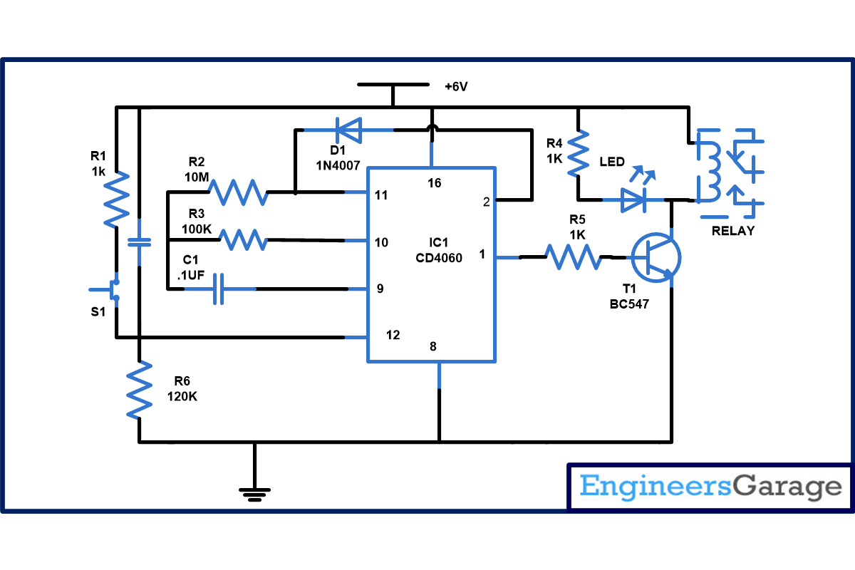
When you come home and press the switch S1, switch S1 is released it will reset the pin 12. When this pin goes high it will start the counter and first output Q4 pin 7 goes high( refer pin diagram) for specific period of time, set with the help R3 and C1. Then pin 5 output goes high similarly all output goes high and when output Q13, pin 1 goes high which will bring the transistor T1 into conduction and relay connected to it will energize and on the bulb(we have connected LED in our circuit) for 20 sec approx. You can connect bulb at any of the output (Q4-Q14) according to your requirement.
From the circuit diagram you can see that we have connected the pin 2 of IC1 to pin 11 with the help of a diode so that when 2 goes high it will disable the counter until reset pin 12 again goes high. So that bulb will only glow when a switch is press.
If you want to increase or decrease the time period for which light remain on. You can do it just by changing the value of resistor and capacitor connected at pin 10 and pin 9. When you increase the value of resistor and capacitor time period will increase and when you decrease the value time period will decrease.
Circuit Diagrams
Project Components
Project Video
Filed Under: Electronic Projects
Filed Under: Electronic Projects


Questions related to this article?
👉Ask and discuss on EDAboard.com and Electro-Tech-Online.com forums.
Tell Us What You Think!!
You must be logged in to post a comment.