Power connectors are specifically designed for the purpose of transferring power from one device to another or from one point to another point of a same unit. Connectors of this category generally have comparatively high voltage, current and temperature ratings. In this article, we will be discussing some of the common power connectors including IEC and DC connectors.
IEC CONNECTOR
You might have noticed that some of the electrical appliances shipped from abroad have incompatible power plug connector with ours. The reason is that the device is not designed or modified for to sell in our market. Different countries have power plug connectors in different size and shapes. Let us take a look at the different standards of plug connectors in use.

Fig. 1: Image showing Power Plug Standards
This variety in connector shape and sizes could have been a headache for multinational manufactures, because for each country they must modify their product. At least they must remove the wire from the main board and replace with one having the intended company’s power plug. This is difficult and non-profitable for the manufactures. People working abroad also face a similar issue, as they can’t bring home any devices from there.
The above mentioned trouble is solved by the International Electro-technical Commission (IEC). The IEC imposed some standard on the power cable male and female connector which connects the power cable to the device, so that whatever the type of plug might be, every power cable is compactable can be connected to the device. We call this IEC standard connector as IEC connectors.

Fig. 2: Image of an IEC standard male and female connector
Now the manufacturers are free to mass produce their same model irrespective of the various plug standard exist around the globe. Before shipping the product to a particular country all they need is to include the power cord with IEC connector at one end and plug type used in the country on other end inside the packet.
The IEC connectors have large and standard current and temperature ratings. These connectors are intended to be used up to 250 Volts. IEC 60320 is the standard defined for the IEC power connectors. Under this standard there are different types of power connectors with different shape and sizes. Each of these connector standards has different current and voltage ratings.
These standards can be identified by their number starting with an alphabet ‘C’. The number next to the ‘C’ is an odd number representing the female connector which follows by a forward slash ‘/’ and an even number representing the male connector. The IEC standard defines the size, shape, current ratings, temperature ratings and the polarization of the connectors.
Now let us discuss about some of the IEC standard connectors.
C1/C2 & C5/C6Connectors
C1/C2 connector
These connectors have only two pins and these pins can be connected in any orientation. There is no earth pin for this power connector standard. The maximum current rating for this standard connector is only 0.2 A. The maximum temperature rating is 70 degree at the pins.

Fig. 3: Diagram for C1/C2 IEC connector

Fig. 4: Image of a C1 IEC connector
These kinds of connectors are mostly used in various models of electric shavers.
C5/C6 connectors
These connectors have three pins including an earth pin. Due to its three pin geometry these connectors are polarized, means they can be connected in only in a single orientation. They have maximum current rating up to 2.5A and can operate at a maximum pin temperature of 70 degrees.

Fig. 5: Diagram for C5/C6 IEC connector
They are commonly called “Mickey Mouse” connectors; take a close look at the above image and you can make out the reason for such a name.

Fig. 6: Image of a C6 IEC connector

Fig. 7: Image of a C5 IEC connector
These connectors are commonly used in Laptop power supplies, small SMPS stc.
C7/C8 & C13/C14 Connectors
C7/C8 connector
These connectors have only two pins. The earth pin is absent in these connectors. They come in both polarized and non-polarized models. The C7/C8 connectors are designed to operate up to 2.5A current at 70 degree pin temperature maximum. The connectors have ‘B’ geometry with non-polarized connectors having both ends rounded and the polarized connector having one of the edge Square shaped.
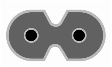

Fig. 8: Diagram of un-polarized and polarized C7/C8 connectors
The un-polarized C8 connector can be inserted into the polarized C7 connector but the polarized C8 connector cannot be connected to the unpolarized C7 connector. It is not recommended to connect an unpolarized connector to a polarized connector, because the device might be designed for a particular power supply polarization and this practice can potentially damage the device.

Fig. 9: Image of a C8 IEC connector

Fig. 10: Image of a C7 IEC connector
They are usually found in small radios, battery operated rechargeable devices, laptop power supplies etc.
C13/C14 connector
The C13/C14 connectors have three pins including an earth pin. Due to its three pin geometry these connectors are polarized. Compared to other standards they can be operated at much higher current up to 10 or 15 amperes. The temperature rating is similar to other standard with a pin temperature of maximum 70 degrees.

Fig. 11: Diagram of C13/C14 connector
These connectors are commonly found in PC cabinets. They are called as “Kettle cords” in some countries may be due to its higher current and temperature ratings. But the temperature rating is actually much lesser than those connectors used in electric kettles.

Fig .12: Image of C13 IEC connector

Fig. 13: Image for C14 IEC connector
These kinds of connectors are widely used in PC cabinet, Monitors, SMPS, UPS, printers and many other electrical devices.
C15/C16 Connectors
C15/C16 connector
These connectors are also called “heat conditioned connectors”. The reason is that they have higher temperature ratings than compared to other IEC connector standard. They also have three pins including the earth pin. They are polarized connectors. They have maximum current rating of 15 amperes at a maximum pin temperature of 120 degrees.

Fig. 14: Diagram of C15/C16 connector
They are also called “Kettle cord connector” because of their higher temperature ratings. They are usually used as power connectors in electric kettles and devices that get too much hot.

Fig. 15: Image of C15 IEC connector

Fig. 16: Image of C16 IEC connector
You might have noticed the small notch like structure in the image of the C15 and C16 connectors, which can be used to differentiate between the C13 and C14 connectors respectively. It is actually a safety feature included, so that the user cannot plug in a lower temperature rated C13/C14 connector to the device and thereby preventing damages including burning up of the connector due to excess heat.
The C15/C16 connectors are widely used in devices which converts electrical energy to heat energy like electrical kettles, electrical irons etc.
So far we have seen different standard of IEC connectors. Now let us see an important feature regarding the standard connectors. The connectors defined in any standard have a defined pin-out and pin-orientation. We have already discussed about pin-out and pin-orientation in the section describing the features of connectors.
The following image is a representation of pin-orientation of a three pin IEC connector as seen from the pin side of the male connector.

Fig. 17: Image showing pin orientation of male IEC
The following image is a representation of pin-orientation of a three pin IEC connector as seen from the pin side of the female connector.
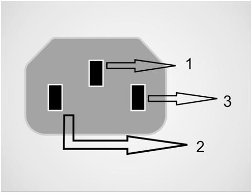
Fig. 18: Image showing pin orientation of male IEC
In an IEC connector the three pins are used for the purpose as listed below.
PIN 1 ——————EARTH
PIN 2 ——————LINE
PIN 3 ——————NEUTRAL
Sample specification:
Current rating —————————— 10 mille ohm
Withstanding voltage ——————– >2kVAC
Voltage rating—————————— 250 V
DC Connectors
DC Connector
DC connector is a specialized connector designed for transferring DC power to a device. They have small current and voltage ratings compared to other power connectors. They are mostly used up to 12 V DC. They are commonly found low power electronic devices. These connectors have male and female types. They male pin is usually has a cylindrical structure with an inner contact and outer contact separated by insulating material.

Fig. 19: Image of Power Connector

Fig. 20: Image of DC socket
The male DC connector is commonly called DC jack and the female DC connector is referred to as DC socket. The DC jack is connected to the wires running down from DC adapters or battery eliminators. The DC socket is soldered into circuit boards into which the DC jack is intending to be connected.

Fig. 21: Image showing DC socket mounted on a PCB
As shown in the above image the DC sockets are usually mounted at the edges of the PCB, so that no other components block the entry of the male pin into the connector. You can always find an ON/OFF switch and a power indicating LED next to the DC socket.
The DC jack is a simple cylindrical structure with two contacts separated by an insulating structure, but the DC socket is not that simple. Most of the DC socket has three pin-outs even though the DC jack has only two contacts. The outer cylindrical contact is GROUND and the inner pin is positive. A circuit symbol for the DC socket is shown in the following figure.

Fig. 22: Circuit symbol of a DC socket
You can make out from the above symbol that the PIN 2 and PIN 3 form a Normally Closed (NC) contact. They become open whenever we insert the male pin into the socket. The function of the above three pins and the reason for such an arrangement is discussed below,
The pin-out of the DC socket
PIN 1 ——————COMMON POSITIVE
PIN 2 ——————ADAPTER GROUND
PIN 3 ——————BATTERY GROUND
Most of the circuit boards have a battery attached to it still we can plug in an external DC adapter to operate the circuit. The DC socket’s three pin structure is used to separate the GROUND terminal of the battery from the GROND terminal of the DC adapter. The positive terminal of both battery and the DC adapter can be connected to the PIN 1 of the DC socket. The PIN 1 and PIN 2 supplies power to the PCB. PIN 3 is where the GROUND of the battery is connected. A similar connection diagram is shown in the following figure.

Fig. 23: Image showing DC socket used to isolate battery from external DC
When there is no DC adapter plugged in, the NC contact of the PIN 3 with the PIN 2 supplies battery power. When the DC adapter is plugged in the PIN 2 is isolated from the PIN 2 and now the PIN 2 is in contact with the DC jacks GROUND pin and the device will work on external DC power.
Sample specification:
Current rating —————————— 1 A
Withstanding voltage ——————– >1000 VAC
Voltage rating—————————— 250 V
Contact resistance ———————— 20 mille ohm
Insulation resistance ——————— 5000 mega ohm
Capacitance ——————————– 1.5 pF
Summary
{C}{C}{C}{C}{C}· {C}{C}{C}{C}{C}The power connectors are used to transfer external power to a unit
{C}{C}{C}{C}{C}· {C}{C}{C}{C}{C}IEC connectors are 250 V connectors and their standards are defined by the International Electro-technical Commission (IEC).
{C}{C}{C}{C}{C}· {C}{C}{C}{C}{C}IEC connectors have high current and temperature ratings.
{C}{C}{C}{C}{C}· {C}{C}{C}{C}{C}IEC connectors are mostly used to couple 250 V AC power.
{C}{C}{C}{C}{C}· {C}{C}{C}{C}{C}DC connectors are used to couple only DC power to the device
{C}{C}{C}{C}{C}· {C}{C}{C}{C}{C}They have very low voltage and current ratings
Filed Under: Tutorials

Questions related to this article?
👉Ask and discuss on EDAboard.com and Electro-Tech-Online.com forums.
Tell Us What You Think!!
You must be logged in to post a comment.