Power factor correction is the method to reduce the lagging power factor in inductive loads by fixing a high value capacitor across the phase and neutral close to the load. When the Voltage and Current are in phase with each other in an AC circuit, the energy from the source is fully converted into another form to drive the load and in this case power factor is in unity. When the power factor drops, the system becomes less efficient. As a rule a drop from unity to 0.9 in the power factor increases the current requirement to 15% or more.
A power factor of 0.7% increases the power requirement to around 40%. This is much severe in the case of inductive loads such as Motors, Refrigerators, Inverters etc. In these inductive loads, current “lags” the voltage leading to “lagging power factor”. But opposite condition occurs if current “leads” the voltage. This is called “leading power factor”. “Power factor correction” is the method to reduce the lagging power factor in inductive loads by fixing a high value capacitor across the phase and neutral close to the load. These capacitors have leading power factor so that it will neutralize the lagging power factor of the load. Power factor correction has the following advantages.
1. Load becomes more efficient
2. Prevents wastage of energy though heat
3. Maintains voltage stability
Over correction
It is important to note that, if the power factor capacitor ( PFC) is connected at the entry point of power supply, say after the meter or in the distribution point, there is chance of “Over correction” when a fraction of the full load is switched on. This over correction causes heavy surge current flows to the load during switching that may destroy the load. So the PFC must be connected close to the inductive load, so that power correction occurs only in that load.
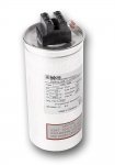
PF correction Capacitor
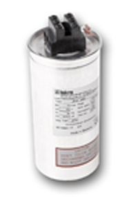
These capacitors have self healing property. That is during momentary faults, small areas of the capacitor electrodes evaporate to restore its function again. There are two types of power factor correction capacitors.
1. Oil filled type in metal case and
2. Epoxy filled in plastic case
These PFCs can operate smoothly at a temperature as high as 70 degree. The PFCs have working voltage of 240 volt AC, 440 volt AC etc. Capacitance of PFC varies between 2 uF to 100 uF. The PFCs are also specified by its “Reacting power” KvAR. Below formulae is used for power factor correction calculation:

PFC connection
Power factor capacitor is connected across the phase and neutral near the inductive load such as motor. Before connecting the PFC, make sure that the capacitor is sufficiently rated to the load capacity. It should be connected to the lines, only if the load is running and drawing current.
Note: Before connecting a Power factor capacitor, seek the opinion of an expert since the many parameters like voltage, current, load capacity etc are involved in power factor correction.
Filed Under: Electronic Projects

Questions related to this article?
👉Ask and discuss on Electro-Tech-Online.com and EDAboard.com forums.
Tell Us What You Think!!
You must be logged in to post a comment.