Different communication technologies are being used for the transmission of information from one end to another depending on the feasibility and needs. Some include Ethernet cables, fiber optics, wireless transmission, satellite transmission, etc. A vast amount of information travels through the entire earth every day and it creates an essential need for a transmission medium that is not only fast but economically reasonable as well. One of the technologies that fit in the above stated criteria is PLCC.
PLCC, Power Line Carrier Communication, is an approach to utilize the existing power lines for the transmission of information. In today’s world every house and building has properly installed electricity lines. 

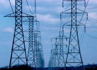
Fig. 1: An Image of Power Line Carrier Communication
By using the existing AC power lines as a medium to transfer the information, it becomes easy to connect the houses with a high speed network access point without installing new wirings.
This technology has been in wide use since 1950 and was mainly used by the grid stations to transmit information at high speed. Now a days this technology is finding wide use in building/home automation as it avoids the need of extra wiring. The data collected from different sensors is transmitted on these power lines thereby also reducing the maintenance cost of the additional wiring. In some countries this technology is also used to provide Internet connection.
History
The idea of using an existing medium to send the communication signals is as old as the telegraph itself. But it had not been possible until the recent decades. The first significant step in the field was when two patents were issued to American Telephone and Telegraph Company in the name of ‘Carrier Transmission over Power Circuits’ in 1920. After four years later in 1924 two other patents were filed for the systems transmitting and receiving communication signals over three phase power lines.
Harsh characteristics of the power cables were the key problem in further development. Researchers were involved to overcome the unpredictable characteristics of the power lines. Since the early 1980, spread spectrum power line communication was the main focus of the research. This technology is now developed far better than that initial improvement and is promising a reliable utilization in home automation and security systems.
Applications of PLCC
PLCC technology can be deployed into different types of applications in order to provide economic networking solutions. Hence merging with other technologies it proves useful in different areas. These are few key areas where PLC communications are utilized:
a. Transmission & Distribution Network: PLCC was first adopted in the electrical transmission and distribution system to transmit information at a fast rate.
b. Home control and Automation: PLCC technology is used in home control and automation. This technology can reduce the resources as well as efforts for activities like power management, energy conservation, etc.
c. Entertainment: PLCC is used to distribute the multimedia content throughout the home.
d. Telecommunication: Data transmission for different types of communications like telephonic communication, audio, video communication can be made with the use of PLCC technology.
e. Security Systems: In monitoring houses or businesses through surveillance cameras, PLCC technology is far useful.
f. Automatic Meter Reading – Automatic Meter reading applications use the PLCC technology to send the data from home meters to Host Central Station.
Operating Principle
The communication device used for the communication over the power lines is a MODEM, commonly known as Power Line MODEM (PLM). It works as both transmitter and receiver, i.e., it transmits and receives data over the power lines. A power line modem not only modulates the data to transmit it over the power lines and but also demodulates the data it receives from the power lines. By using modulation techniques, binary data stream is keyed on to a carrier signal and then coupled on to the power lines by PLM. At the receiver end another PLM detects the signal and extracts the corresponding bit stream.

Fig. 2: Figure Showing Working of PLCC System
The above image shows the working of a PLCC system. Data is processed before transmission on power lines according to the above figure. First data is modulated & filtered and then by using couplers, it is sent over the power lines.
PLC Modem
PLC Modems/Transceivers
PLC Transceiver is the key component of a PLCC system. It is the device which transmits & receives data to & from the power lines and acts as a hub between the power stations and our Computers/Network utilization devices. They are wired with the electrical voltage lines at home or business and work on two modes – transmit mode and receive mode. In transmit mode, they simply receive data from receiver end installed on the same network and further transmit them. In receive mode, they work the opposite way.
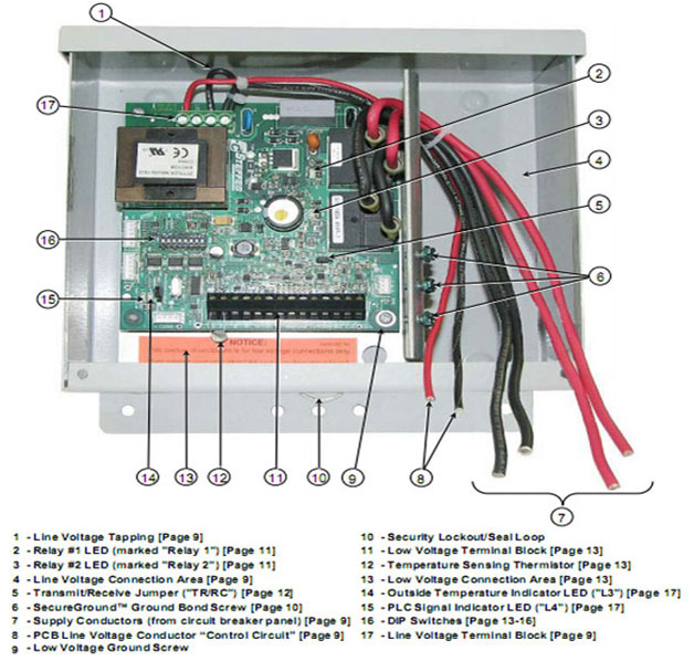
A number of companies provide PLC transceivers and other networking devices for PLCC communication. A PLC transceiver is shown in the following image.

Fig. 3: An Image of PLC Transceiver
Modulation & Superimposition
Modulation Techniques
As mentioned earlier, characteristics of the power line channel continuously vary with time and load. So conventional modulation techniques like ASK, FSK or PSK cannot be employed with them. PLCC needs a technique that can deal with the unpredictable attenuation and phase shifts.
Modulation techniques that opt lower frequency ranges of 35 KHz to 95 KHz can perform better as compared to the ones using the whole available frequency band. OFDM (Orthogonal Frequency Division Multiplexing) is the modulation technique that is used in HomePlug specification network appliances. In OFDM, information is modulated on to multiple carriers, where each carrier occupies its own frequency in the range of 4.3 to 20.9 MHz. Incoming bit stream is demultiplexed into N number of parallel bit streams each with 1/N of original bit rate which are then modulated on N orthogonal carriers. By using multiple carriers at a time, the modulation technique uses the available spectrum most efficiently. During the transmission, each frequency is monitored and if any interference, noise or data loss occurs, the responsible frequency is removed. However this technique does not perform well when a large attenuation and jamming occurs in the communication channel, but still it can be very efficient comparatively.
How signals are superimposed on Power Lines?
There are two different ways by which we can connect a PLC unit with the power lines – capacitive coupling and inductive coupling. In capacitive coupling, a capacitor is used to superimpose the modulated signal on to the network’s voltage waveform. Another way is inductive coupling which employs an inductor to couple the signal with the network’s waveform.
No physical connection is required to establish inductive coupling. This makes it safer as compared to capacitive coupling. However this method has higher tendency to lose the signal during coupling.
Technical Parameters
Important Technical Parameters in PLC Communication
Noise on Residential Power Circuit (RPC):
A variety of noises may occur during the communication caused by the home appliances. Following are some of the types:
1. Noise synchronous to the power system frequency (50Hz or 60 Hz) – This type of noise is generated because of different kind of switching devices.
2. Noise with a smooth spectrum – The sources of such type of noise are the appliances that are not operating synchronously with the power line frequency. For example the small motors with several windings can generate such type of noise.
3. Single Event Impulse Noise – Switching of devices, that contain a capacitor, generates such type of noise. The reason is sudden discharge of the capacitor in the RPC.
4. Periodic Noise – The type of noise is generated by fluorescent lights, television receivers etc.
These are some ways to reduce the noise in between the communication over power lines:
a. Implementation of Forward Error Correction (FEC) codes with interleaving can reduce the noise in category 1, 2 and 3.
b. Frequency Hopping with the FEC coding can be implemented to deal with the unknown frequencies.
c. While modulating the signal on to the power lines, television line frequencies should be avoided.
Signal to Noise Ratio:
Signal to Noise Ratio (SNR) is a measurement of quality of the signal. It indicates the amount of the noise in a signal. SNR can be formulated in the following way:
SNR = Received Power / Noise Power
Increasing SNR means increasing the performance of the communication system. By applying noise filters on household appliances, the noise entering into the power system can be reduced. However it will increase the cost of the appliances but is a better solution to improve overall performance.
Signal Attenuation:
Signal attenuation is basically the reduction in strength of the signal. A signal attenuation of about 100dB/Km occurs for low voltage power lines and 10dB/km for high voltage lines. It creates a need of continuous repeaters over a fixed distance. A number of factors that are responsible for signal attenuation include distance, time, frequency of the signal, etc.
PLCC in Meter Reading
How PLCC technology is used in meter reading?
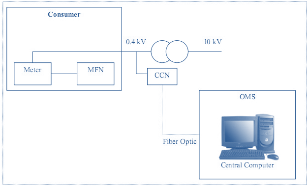
Automatic Meter Reading using PLCC technology is quite useful as it saves a lot of human efforts and also makes the whole system more efficient. The automatic meter reading system consists of three components, namely, Multifunction Node (MFN), Concentrator & Communication Node (CCN) and Operation & Management System (OMS). Different components and their inter-connections are shown in the figure.

Fig. 4: Figure Showing Automatic Meter Reading System Components and Interconnection between them
MFN is a unit installed in household meters, either incorporated in the meter itself or externally connected to it. Its function is to take reading of the meter on an hourly basis and store it in a memory chip. CNN is another part which manages all MFNs within a particular area and collects meter readings from all MFNs. It is generally installed on substations and needs a computer. The computer is installed with Operation and Management System (OMS) which further manages all the data and meter readings from CNNs.
PLCC Technology in Home Automation
In modern homes, there is a huge requirement of sending digital information, audio, and video all over the home. Running new wires to support this will increase the burden and cost of maintenance. To overcome this, PLCC is the right choice to implement home automation concept. Home automation or also known as Smart Home technology is a collection of systems and devices in a home that have an ability to interact with each other or function individually in order to be optimized in best way. Using PLCC technology, existing power wirings of the house is used to connect home appliances with each other as well as with internet.

Fig. 5: Figure Showing PLCC Based Home Automation Simple Architecture
Architecture of a PLCC based home automation system is shown in the above image. Various home appliances are connected within a loop through the existing power cables. This technology can connect each device with the network which is connected to an AC outlet. All appliances are also connected with a centralized control panel which controls them.
PLCC Standards
Proper standardization makes a technology comprehensive and deployable. A few standards pertaining to PLCC exist in different parts of the world.
1. European Committee for Electrotechnical Standardization (CENELEC)
Countries from the Western Europe formed a standard known as CENELEC standard to standardize the issues and concerns related to power line communication. This standard defines standards for allowed frequency ranges and output voltages for the communication over power lines.
A frequency range of 3 to 148.5 KHz is allowed for the communication and this range is further divided in 5 sub-bands. These are according to the following table:
|
Band
|
Frequency Range
|
Usage
|
|
|
3KHz – 9KHz
|
This range is restricted to the Energy Providers.
|
|
A-Band
|
9KHz-95KHz
|
Restricted to the energy providers and their concession holders
|
|
B-Band
|
95KHz-125KHz
|
Restricted to the energy providers customers. There is no access rule defined for this frequency range.
|
|
C-Band
|
125KHz-140KHz
|
Restricted to energy providers customers. Simultaneous operations on multiple systems are possible for this frequency band, A protocol named Carrier Sense Multiple Access Protocol is defined for this using a frequency of 132.5KHz.
|
|
D-Band
|
140KHz-148.5KHz
|
Restricted to customers. No access protocol is defined for this band.
|
2. Federal Communications Commission (FCC)
FCC standardizes the frequency ranges and transmitted power ranges for the power line communications in North America. The allowed base frequencies range from 0 to 530 KHz.
3. HomePlug Powerline Alliance
HomePlug Powerline Alliance is a group of companies dedicated to improve the technology for the networking and communication over power lines. In June 2001, first specification named HomePlug 1.0 was launched. The standard uses a physical layer protocol (PHY) based on 128 equally divided carrier OFDMs (Orthogonal Frequency Division Multiplexing) from a frequency range of 0 to 25MHz. It uses concatenated Viterbi and Reed Solomon coding for payload data, Turbo product codes for control data and BPSK, DBPSK, DQPSK or ROBO modulation with a cyclic prefix for modulation of the data.
4. IEEE 1901
Institute of Electrical and Electronics Engineers (IEEE) stated a standard named IEEE 1901 for high speed power line communications. This group was formed in 2005 and gave its first standard in 2010 which includes two different physical layers, first one based on OFDM modulation and the other one based on wavelet modulation. Network devices that employ only OFDM physical layer will not be interoperable with the device that employ Wavelet physical layer.
Advantage and Disadvantage:
In order to completely analyze the advantages and disadvantages of PLCC technology, we look into its basic application that is access to telecommunication networks. From the economic standpoint, it is very reasonable to use a pre installed wired network instead of running new wires. It certainly reduces a lot of time & money and so is the biggest advantage of the technology.
In many countries, PLCC is becoming a reliable high speed source to get Internet. And in some places, especially in remote areas, PLCC technology thankfully made it possible to avail internet connections.
Power line communication is quite different in characteristics than the conventional dedicated wirings. Comparatively, it is a harsh medium and data transfer through it can create a lot of problems. Household appliances like halogen tubes, washing machines, televisions, etc. can become prone to an unpredictable noise and interference in the transmission. Continuous plugging and unplugging of electronic devices makes power line characteristics vary constantly.
Filed Under: Articles


Questions related to this article?
👉Ask and discuss on Electro-Tech-Online.com and EDAboard.com forums.
Tell Us What You Think!!
You must be logged in to post a comment.