In previous articles (including here, here, and here), we discussed the different types of filters available, including examples. If you’ve followed along, you should have an understanding of the frequency components (i.e., attenuating high frequencies when using a low pass filter and the passing frequencies for a high pass filter). You should also be aware of the four basic hardware filters (LPF, HPF, BPF, and BRF ) and their uses, and be able to differentiate between theoretical and practical implementations.
In this article, we’ll demonstrate real-life applications of filters. The basics of hardware filter design are relatively simple, but additional parameters come to play when going from theory to application. For example, consider the design of a low-pass filter. It appears simple with only two passive components, a resistor and a capacitor. But the transition period of the cutoff frequency will be extremely slow because this is a first-order filter.
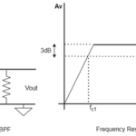
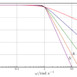
The transition period of the filter is defined as the period between the passband and stopband. The curve of amplitude compared to the frequency goes from high to low, as shown in the figure below. A low pass filter 1KHz cutoff frequency will pass the frequency components to 10KHz, but with less amplitude. A higher-order filter can be used to reduce this transition period.
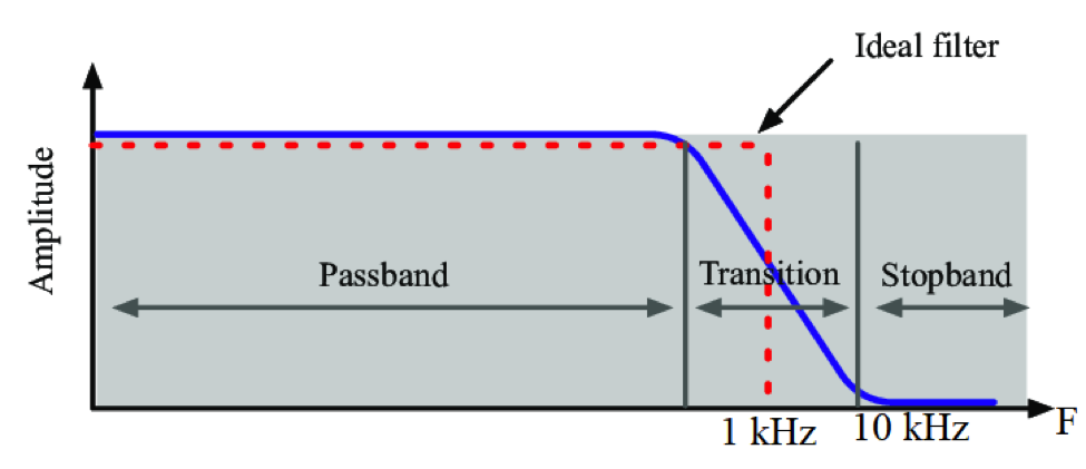
The transition period of a low pass filter.
That’s enough theory. Now, let’s implement a low pass filter followed by a band reject filter.
The average frequency of a typical male voice is 120Hz and female voice is 200Hz. For this project, we’ll use audio of a human voice, adding a 10KHz frequency of noise afterward. A low-pass filter is used to pass the low frequency human voice and stop the high-frequency 10KHz noise.
The low pass filter is designed as an RC filter, and the cut-off frequency of this low-pass filter is 1Khz.
Electronic components:
1. TDA2030 audio amplifier
2. 5V supply (power bank)
3. Boost converter for TDA2030
4. Speaker
The setup…
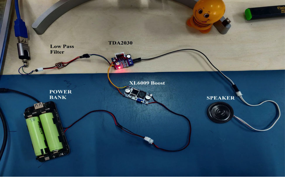
The low pass filter setup.
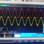
Below you’ll find a video of the completed project. The audio of speech is part of our data, as is the 10KHz sine wave noise. The difference between the audio and noisy signal (audio + 10KHz sine wave) can be observed without the low pass filter.
After applying the low pass filter, the audio signal noise is removed or attenuated.
Note how the audio becomes clearer after the low-pass filter is employed. This means there were more high-frequency noise signals in the audio signal (speech) than the 10KHz sine wave.
The low-pass filter removes the high-frequency components of the audio signal.
The video…
Another experiment
A different application is used in the next implementation of the low-pass filter. In electronics several types of converters, including:
- The step-down converter, which converts high voltage to low voltage
- The step-up, which converts low voltage to high voltage.
One of the more famous step-down converters is the LM2596.
Explanation
In this experiment, we will “step down” 22 to 5 volts by using the LM2596 module. A resistive load of 2.5 Ohm is used to draw the current from this module. When drawing a high current (like two or three amps) from the LM2596, ripples can occur at the output.
By using the LC low pass filter, it’s possible to remove these ripples from the LM2596 module.
This image demonstrates 20V input and 5V output voltage from the LM2596.
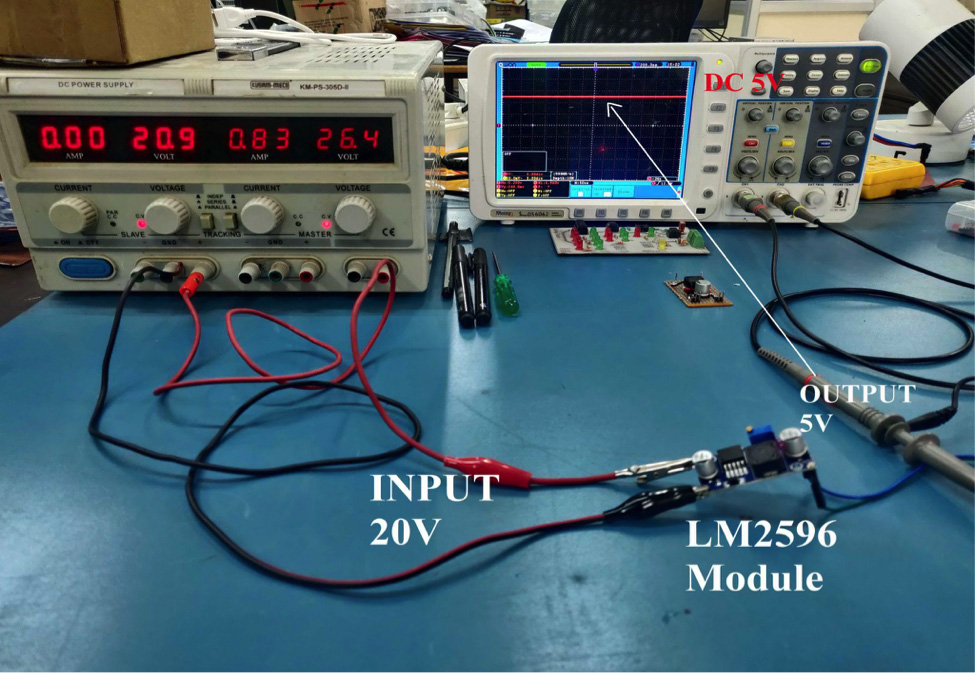
A 5V output of DC voltage from the LM2596.
Now, let’s connect a 2.5 Ohm load at the output of the LM2596 module, while drawing about two amps of current from the LM2596 module. The current can be calculated using Ohm’s Law.
V = IxR
I = 5/2.5 Amps.
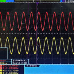
After connecting the load, it draws a calculated current, and a ripple is displayed on the oscilloscope in the 5V output.
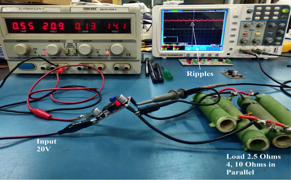
Ripples on the output, after connecting a 2.5- and 4.10-ohm load in parallel.
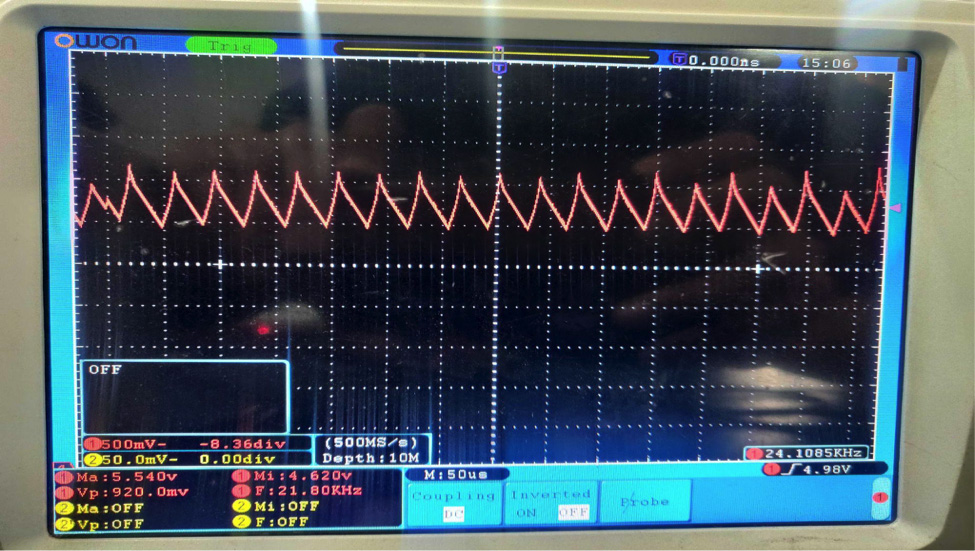
A close-up view of ripples on the output oscilloscope screen.
These ripples are 20 kHz, as displayed on the oscilloscope. So, how do we remove these ripples? Let’s try a low pass filter.
According to the application, we’ll need pure DC at the output, and DC has zero frequency components. But a low pass filter should do the trick. A 1, 2, or 3 Khz filter can be used because the ripple frequency is high. We’ve chosen an LC low pass filter because of the output’s high-current requirements.
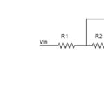
An LC filter is designed per the below figure.
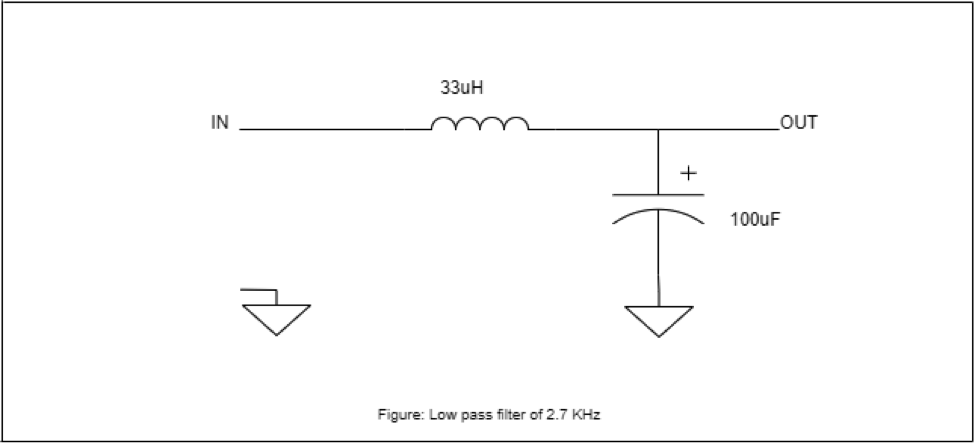
A 2.7 KHz low pass filter
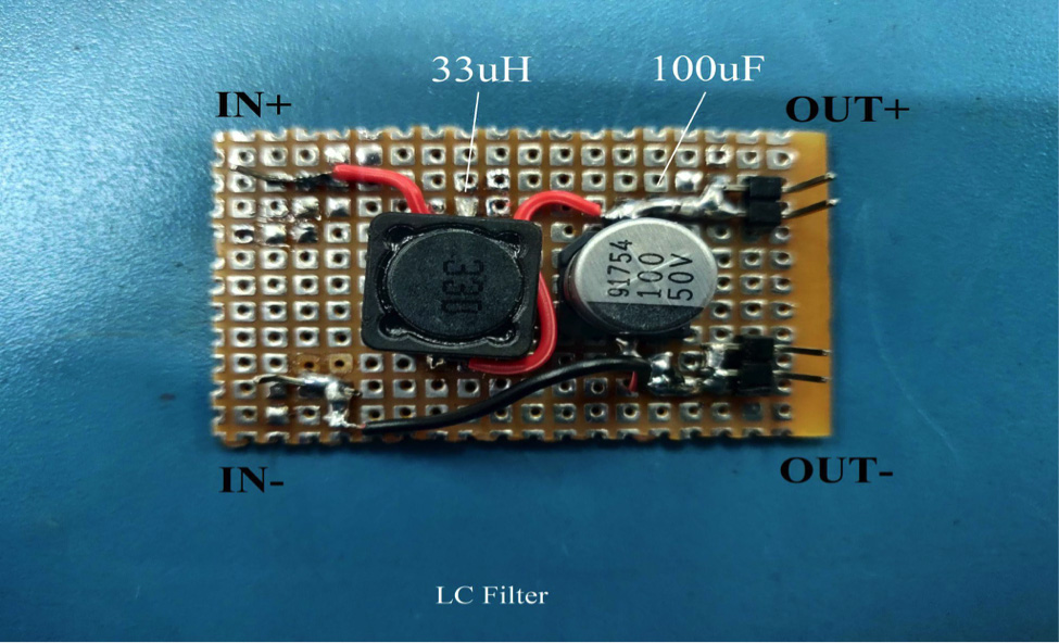
An LC filter on the PCB
Let’s connect this designed low pass filter at the output of the LM2596 module and the load.
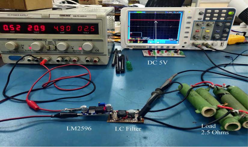
The full setup, including the low-pass filters with the LM2596 module and the load to remove ripples.
After connecting the low pass filter at the output of the LM2596, the ripples disappear. The project was a success! The low-pass filter removed the high-frequency components from the DC voltage. This means that are filter was designed correctly and is working well.
You may also like:

Filed Under: Hardware Filters, Tech Articles, Tutorials

Questions related to this article?
👉Ask and discuss on Electro-Tech-Online.com and EDAboard.com forums.
Tell Us What You Think!!
You must be logged in to post a comment.