Engineers Garage

  • Electronic Projects & Tutorials
    • Electronic Projects
      • Arduino Projects
      • AVR
      • Raspberry pi
      • ESP8266
      • BeagleBone
      • 8051 Microcontroller
      • ARM
      • PIC Microcontroller
      • STM32
    • Tutorials
      • Audio Electronics
      • Battery Management
      • Brainwave
      • Electric Vehicles
      • EMI/EMC/RFI
      • Hardware Filters
      • IoT tutorials
      • Power Tutorials
      • Python
      • Sensors
      • USB
      • VHDL
    • Circuit Design
    • Project Videos
    • Components
  • Articles
    • Tech Articles
    • Insight
    • Invention Stories
    • How to
    • What Is
  • News
    • Electronic Product News
    • Business News
    • Company/Start-up News
    • DIY Reviews
    • Guest Post
  • Forums
    • EDABoard.com
    • Electro-Tech-Online
    • EG Forum Archive
  • DigiKey Store
    • Cables, Wires
    • Connectors, Interconnect
    • Discrete
    • Electromechanical
    • Embedded Computers
    • Enclosures, Hardware, Office
    • Integrated Circuits (ICs)
    • Isolators
    • LED/Optoelectronics
    • Passive
    • Power, Circuit Protection
    • Programmers
    • RF, Wireless
    • Semiconductors
    • Sensors, Transducers
    • Test Products
    • Tools
  • Learn
    • eBooks/Tech Tips
    • Design Guides
    • Learning Center
    • Tech Toolboxes
    • Webinars & Digital Events
  • Resources
    • Digital Issues
    • EE Training Days
    • LEAP Awards
    • Podcasts
    • Webinars / Digital Events
    • White Papers
    • Engineering Diversity & Inclusion
    • DesignFast
  • Guest Post Guidelines
  • Advertise
  • Subscribe

Practical implementation of low-pass and high-pass filter

By Ayush Jain January 11, 2023

In today’s electronic devices, many practical applications use hardware filtering implementation. These applications include electrocardiograms (ECG), image processing cameras, etc. Electrocardiograms are medical devices that record the human heart’s activity using a noninvasive approach by encoding heartbeat into signals. But before reading information from these electrical signals, they are filtered out from unwanted noisy signals introduced by the environment, using many hardware filters like low-pass, high-pass, and notch filters.

In this article, we will try to practice using hardware electronics components by designing some hardware filters to capture their input and output waveforms on the oscilloscope.

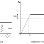
Low-pass filter: As we know, the low-pass filter passes the low-frequency components from any signal without attenuation (decrease in power). Low-frequency components can be defined using the cutoff frequency of the designed hardware filter.

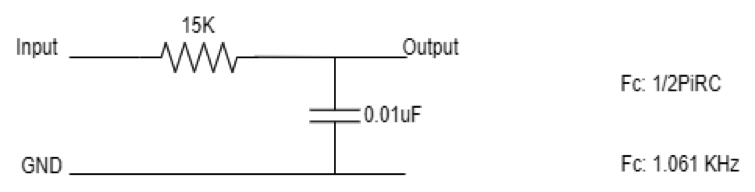
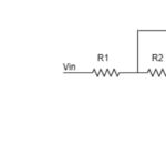
Fig. 1: The image shows the specification of the designed First order low-pass filter

The above design has a cutoff frequency of approx 1KHz. So, this low-pass filter will attenuate the frequencies above 1KHz and pass the frequency components below 1KHz.

The input signal has a peak-to-peak amplitude of 5 Volt.

In the oscilloscope screen below, the input is in red, and the output is in yellow. And it is clearly shown that a low frequency of 500Hz is passed through the above-designed filter, which has a cutoff frequency of 1KHz.

There is no attenuation in the output signal.

Red prob  – Input signal frequency
Yellow prob – Output signal frequency

Fig. 2: The image shows output variation for a low frequency of 500Hz is passed through the above-designed filter

But when the input signal frequency is increased from 500 Hz to 5KHz. The high-frequency components are attenuated. This can be seen in the figure below. The signal amplitude is attenuated from 5 V to 1 V.

Fig.3: The image shows the attenuated output when the input frequency is increased from 500 Hz to 5KHz

We have studied the first-order low-pass filter, which is designed using a resistor and a capacitor in series. But sometimes, it is not necessary that all the noisy frequency components can be removed using only a single-order low-pass filter.

Thus a designer needs a second-order filter.

Second-order low-pass filter
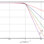
The second-order low-pass filter can be designed by adding one more low-pass filter stage to the first-order low-pass filter. Higher-order low-pass filters are obtained to remove or attenuate high-frequency components from the input signal completely.

A given formula calculates the cutoff frequency of the second order.

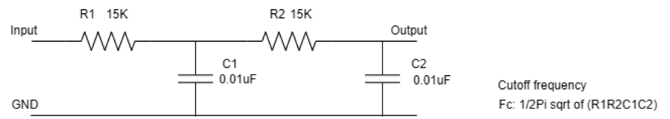
Fig.4: The image shows the specification of the second-order filter

Fig.5: Image shows input and output on oscilloscope screen for second-order filter

In the above figure, a signal of frequency 300 Hz is passed through a second-order filter with a cutoff frequency of 1 kHz. Thus the above circuit passes the signal frequency below 1 kHz and stops the frequency components above 1 kHz.

When a signal of frequency 3 kHz is passed through the above-designed filter. The output signal is almost lost or attenuated because this low-pass filter attenuates the frequency above its cutoff frequency of 1 kHz.

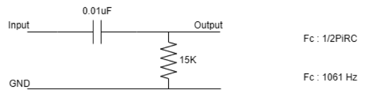
Fig. 6: The image shows the final attenuated signal for the designed filter

High-pass filter:  High pass filter is the functional complement of the low-pass filter. As we have studied, the high-pass filter has high-frequency components in the pass band and low-frequency components in the stop band.

A high pass filter is designed, which has a cutoff frequency of approx 1KHz. The electronic components and their value used in the design are shown in the figure below.

Fig. 6: The image shows the specification of the designed high-pass filter.

When a signal of 500 Hz is passed through the high pass filter, which has a cutoff frequency of around 1 kHz, This filter attenuates the input signal, as shown in the below figure. The signal’s amplitude goes down to 2.80 V peak-to-peak from 4.64 V.

Red prob   – Input signal frequency
Yellow prob   – Output signal frequency

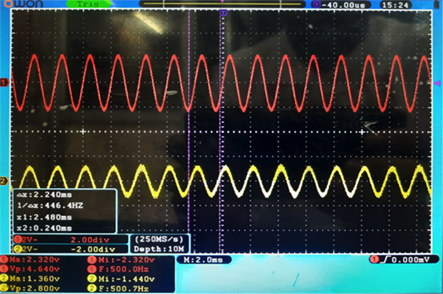
Fig. 7: Image shows attenuated output signal for 500Hz input signal at cutoff frequency 1KHz

And when a signal with high-frequency components is passed from the above circuit. It is observed that the high-frequency components are passed without any attenuation from the filter.

This can be seen in the figure below.

Fig. 8: Image shows the output for high-frequency input for high pass filter

In the above figure, an input signal is 2 kHz (shown in RED color), and the filtered (Output) signal is also 2 kHz (Shown in yellow color). This is how the high-pass filter works. 

You may also like:


  • A filter design example

  • Problems in filter implementation

  • What are the two types of hardware filters?

  • Types of filter responses

  • What are hardware filters and their types?

  • Transfer function, quality factor, and cut-off frequency

Filed Under: Hardware Filters, Tutorials


Next Article

← Previous Article
Next Article →

Questions related to this article?
👉Ask and discuss on EDAboard.com and Electro-Tech-Online.com forums.


Tell Us What You Think!! Cancel reply

You must be logged in to post a comment.

EE TECH TOOLBOX

“ee
Tech Toolbox: Internet of Things
Explore practical strategies for minimizing attack surfaces, managing memory efficiently, and securing firmware. Download now to ensure your IoT implementations remain secure, efficient, and future-ready.

EE Learning Center

EE Learning Center
“engineers
EXPAND YOUR KNOWLEDGE AND STAY CONNECTED
Get the latest info on technologies, tools and strategies for EE professionals.

HAVE A QUESTION?

Have a technical question about an article or other engineering questions? Check out our engineering forums EDABoard.com and Electro-Tech-Online.com where you can get those questions asked and answered by your peers!


RSS EDABOARD.com Discussions

  • Will this TL084C based current clamp circuit work?
  • ADS optimization cockpit window does not open
  • Voltage mode pushpull is a nonsense SMPS?
  • How to determine the maximum PAD frequency ?
  • Xiaomi Mijia 1C Robot problem of going backwards while working

RSS Electro-Tech-Online.com Discussions

  • Wideband matching an electrically short bowtie antenna; 50 ohm, 434 MHz
  • Curved lines in PCB design
  • using a RTC in SF basic
  • PIC KIT 3 not able to program dsPIC
  • Siemens large industrial PLC parts

Featured – RPi Python Programming (27 Part)

  • RPi Python Programming 21: The SIM900A AT commands
  • RPi Python Programming 22: Calls & SMS using a SIM900A GSM-GPRS modem
  • RPi Python Programming 23: Interfacing a NEO-6MV2 GPS module with Raspberry Pi
  • RPi Python Programming 24: I2C explained
  • RPi Python Programming 25 – Synchronous serial communication in Raspberry Pi using I2C protocol
  • RPi Python Programming 26 – Interfacing ADXL345 accelerometer sensor with Raspberry Pi

Recent Articles

  • AC-DC power supply extends voltage range to 800 V DC
  • Infineon’s inductive sensor integrates coil system driver, signal conditioning circuits and DSP
  • Arm Cortex-M23 MCU delivers 87.5 µA/MHz active mode
  • STMicroelectronics releases automotive amplifiers with in-play open-load detection
  • Convection-cooled power controller integrates EtherCat connectivity

EE ENGINEERING TRAINING DAYS

engineering

Submit a Guest Post

submit a guest post
Engineers Garage
  • Analog IC TIps
  • Connector Tips
  • Battery Power Tips
  • DesignFast
  • EDABoard Forums
  • EE World Online
  • Electro-Tech-Online Forums
  • EV Engineering
  • Microcontroller Tips
  • Power Electronic Tips
  • Sensor Tips
  • Test and Measurement Tips
  • 5G Technology World
  • Subscribe to our newsletter
  • About Us
  • Contact Us
  • Advertise

Copyright © 2025 WTWH Media LLC. All Rights Reserved. The material on this site may not be reproduced, distributed, transmitted, cached or otherwise used, except with the prior written permission of WTWH Media
Privacy Policy

Search Engineers Garage

  • Electronic Projects & Tutorials
    • Electronic Projects
      • Arduino Projects
      • AVR
      • Raspberry pi
      • ESP8266
      • BeagleBone
      • 8051 Microcontroller
      • ARM
      • PIC Microcontroller
      • STM32
    • Tutorials
      • Audio Electronics
      • Battery Management
      • Brainwave
      • Electric Vehicles
      • EMI/EMC/RFI
      • Hardware Filters
      • IoT tutorials
      • Power Tutorials
      • Python
      • Sensors
      • USB
      • VHDL
    • Circuit Design
    • Project Videos
    • Components
  • Articles
    • Tech Articles
    • Insight
    • Invention Stories
    • How to
    • What Is
  • News
    • Electronic Product News
    • Business News
    • Company/Start-up News
    • DIY Reviews
    • Guest Post
  • Forums
    • EDABoard.com
    • Electro-Tech-Online
    • EG Forum Archive
  • DigiKey Store
    • Cables, Wires
    • Connectors, Interconnect
    • Discrete
    • Electromechanical
    • Embedded Computers
    • Enclosures, Hardware, Office
    • Integrated Circuits (ICs)
    • Isolators
    • LED/Optoelectronics
    • Passive
    • Power, Circuit Protection
    • Programmers
    • RF, Wireless
    • Semiconductors
    • Sensors, Transducers
    • Test Products
    • Tools
  • Learn
    • eBooks/Tech Tips
    • Design Guides
    • Learning Center
    • Tech Toolboxes
    • Webinars & Digital Events
  • Resources
    • Digital Issues
    • EE Training Days
    • LEAP Awards
    • Podcasts
    • Webinars / Digital Events
    • White Papers
    • Engineering Diversity & Inclusion
    • DesignFast
  • Guest Post Guidelines
  • Advertise
  • Subscribe