Introduction:
In many machinery industries, the motors (machines) should start at different times, like some machines start at a time some other machines start at different time, some may stop at different time and likewise. To control this machines based on timings, one or more workers is required to be there. Workers may maintain timings to start or stop the machine. But if worker failed to do so it may result in loss to industry.
So to make this system automated based on wireless technology using which only one person can control machine, we can adapt this basic technique.
The new approach in this project is, introducing wireless technology to control machine in different type of machinery industries. Using only one remote control we can start/stop the machines based on desired timings.
Description:
In this project, four motors are connected to receiver circuit using motor driver circuits. Receiver circuit consists of Arduino micro controller RF Rx module and RF decoder chip HT12D. When transmitter sends data by changing data pin state the Arduino reads that change when it gets received data from HT12D, and then it performs particular operation on motors.
In programming, I programmed different combinations to start and stop the motors with different delays. When we are dealing with machine, the most important factor is to specify the delay. This project is mainly depends on time delay, so take care while specifying delay. And also take care about motor driver circuits.
So let us start and see how this is done. First of all, collect following components and equipments.
Required components and equipments:
Sr. no. Name of component Required quantity
1 RF Tx module(434Mhz) 1
2 RF Rx module(434Mhz) 1
3 HT12E 1
4 HT12D 1
5 LED 1
6 Resistor – 1KΩ (Quarter watt) 12
7 Resistor – 1MΩ (Quarter watt) 1
8 Resistor – 50KΩ (Quarter watt) 1
9 Pushbutton 4
10 DC motors 4
11 Battery – 9V 1
12 Battery – 12V 1
13 L293D 2
14 Opto-coupler(MCT12E827Q) 8
15 Bread board 3
16 Arduino development board 1
17 connecting wires
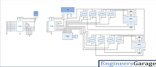
Circuit diagram:
To build above circuit follow the step by step procedure
Procedure:
Transmitter section:
Step1: connect the four push buttons to the data input pins (10,11,12,13) of HT12E, with pull down resistors of 1 KΩ.
Step2: connect 1MΩ resistor between 15 and 16 pins of HT12E.
Step3: connect 17 pin to the 2nd pin of RF transmitter, and 14 pin connect to the ground.
Step4: 1-8 pins of HT12E are address pins, all are connected to ground. Pin 18 is connected to Vcc and pin 9 is connected to ground.
Step5: Connect RF Tx module’s pin 1 to the ground, pin 3 to the Vcc and pin 4 to the antenna.
Receiver section:
Step1: connect the data output pins 10,11,12,13 of decoder HT12D to the Arduino digital pins as inputs (10,11,12,13), and connect pins 9,8,7,6 of Arduino to 1st pin of each opto-coupler. These pins will drive inputs of motor driver L293D1 to control 1st and 2nd motors. And Arduino pins 5,4,3,2, connected to the opto-couplers to drive 3rd and 4th motors through another motor driver L293D2
Step1: connect 5th pin of each opto-coupler to Vcc and 2nd pin to the ground.
Step1: connect 4th pin of each opto-coupler to the motor driver input pins (2,7,10,15). For both motor drivers input pins are same but input pins from Arduino are different
Step2: connect pins 3,4,12,13 of L293D to ground and enable pins (1,9) to Vcc (+5V). Pin 16 should be also connected to Vcc as its power supply for chip.
Step3: connect pins 3,6 of L293D to motor1 and pins 11,14 to motor2. To drive motor with 12V supply, connect the +Ve terminal of 12V battery to the 8th pin of L293D.
Step4 : connect 50KΩ resistor between decoder 15 and 16 pins of HT12D.
Step5: connect 14 pin of decoder to the 2nd pin of RF Rx module, and 17 pin connected to the LED indicator (it will glow when signal is received)
Step6: 1-8 pins of HT12D are address pins, they all are connected to ground. Connect pin 18 to Vcc and pin 9 to ground
Step7: Connect RF Rx module’s 1, 6, 7 pins to the ground, pins 4 & 5 to the Vcc and pin 8 to the antenna.
After building the circuit, now let us see how this circuit works
Working:
1. The HT12E encoder inputs are controlled by switches, this parallel data converted by encoder into serial data and fed to pin 2 of Tx module input from the 17th pin of encoder.
2. Transmitted data is ASK modulated signal the data present in variations of the amplitude. The receiver within the range can receive the ASK signal and generates serial data same as at transmitter and fed to 14th pin of decoder (HT12D).
3. This serial data is converted in to parallel data by the decoder and the parallel data is available as output to pins 10, 11, 12 and 13.
4. This parallel data is given as input to arduino micro controller and it generates output on 6-7-8-9 pins. This pins are given as input to motor driver L293D through opto coupler
5. Motor driver L293D has two H-bridge circuits in side, each one controls one DC motor. L293D has two supply pins 16 and 8. 16th pin is for IC voltage supply and 8th pin is for motors power supply.
6. The decoder pins 10 and 11 controls the motor 1. When 10 and 11 pins are in the combination of logic 00 the motor is stop, if logic combination is 01 then motor rotates in clock wise direction and if logic combination is 10 then motor rotates in anti clock wise direction. Same for motor 2 that is connected to 12 and 13 pins.
7. In this project we are connecting four motors (M1, M2, M3, M4). The aim is to control this motors with different delays. In many industries like textile industry different motors start with different delays to do different type of operations.
8. In this project there are three type of motor operations programmed. First one is starting all motors one by one after some delay with manual stop button. In second, all motors start at a time and after some delay all motors stop also at a time automatically. There is no need of manual stop button.
9. In third and final operation, all motors start at a time but stops automatically at different time.
10. All these operation totally based on microcontroller programming, so here we are trying to say that importance of delay and heavy circuits like motor driver circuits also we can control wirelessly with simple RF remote control.
Pictures:


Some of the precautions that should be taken while developing this project are
Precautions:
1. Address lines should be same at both transmitter and receiver side.
2. At transmitter 14th pin of HT12E should be connect to ground or connect a switch between ground and the 14th pin to reset the encoder.
3. At transmitter side resistor between 15 and 16 pins of HT12E should be between 750MΩ to 1MΩ and at receiver side resistor between 15 and 16 pins of HT12D should be between 30KΩ to 50KΩ.
4. Incase if you want to use any other battery please check the data sheets of HT12E/HT12D before.
5. When connecting L293D take care about power and ground pin connections.
6. Apply 12V at 8th pin of L293D.
Project Source Code
Project Source Code
###
//decoder 10,11,12,13 output pins connected to arduino 10,11,12,13 digital pins as input.int tx1 = 6;int tx2 = 7;int tx3 = 8;int tx4 = 9;//decoder 10,11,12,13 output pins connected to arduino 6,7,8,9 digital pins as input.int m11 = 2;int m12 = 3;int m21 = 4;int m22 = 5;int m31 = 10;int m32 = 11;int m41 = 12;int m42 = 13;void setup(){pinMode(tx1,INPUT);pinMode(tx2,INPUT);pinMode(tx3,INPUT); // decoder output microcontroller reading as input.pinMode(tx4,INPUT);pinMode(m11,OUTPUT);pinMode(m12,OUTPUT);pinMode(m21,OUTPUT); // led's as output.pinMode(m22,OUTPUT);pinMode(m31,OUTPUT);pinMode(m32,OUTPUT);pinMode(m41,OUTPUT); // led's as output.pinMode(m42,OUTPUT);Serial.begin(9600);}void loop(){// reading data and storing in avariable for further use.int Tx1 = digitalRead(tx1);int Tx2 = digitalRead(tx2);int Tx3 = digitalRead(tx3);int Tx4 = digitalRead(tx4);if (Tx1 == HIGH ){digitalWrite(m11,LOW);digitalWrite(m12,HIGH);delay(1000);digitalWrite(m21,LOW);digitalWrite(m22,HIGH);delay(2000);digitalWrite(m31,LOW);digitalWrite(m32,HIGH);delay(3000);digitalWrite(m41,LOW);digitalWrite(m42,HIGH);delay(4000);} else if (Tx2 == HIGH){digitalWrite(m11,LOW);digitalWrite(m12,HIGH);digitalWrite(m21,LOW);digitalWrite(m22,HIGH);digitalWrite(m31,LOW);digitalWrite(m32,HIGH);digitalWrite(m41,LOW);digitalWrite(m42,HIGH);delay(3000);digitalWrite(m11,LOW);digitalWrite(m12,LOW);digitalWrite(m21,LOW);digitalWrite(m22,LOW);digitalWrite(m31,LOW);digitalWrite(m32,LOW);digitalWrite(m41,LOW);digitalWrite(m42,LOW);delay(1000);} else if (Tx3 == HIGH){digitalWrite(m11,LOW);digitalWrite(m12,HIGH);digitalWrite(m21,LOW);digitalWrite(m22,HIGH);digitalWrite(m31,LOW);digitalWrite(m32,HIGH);digitalWrite(m41,LOW);digitalWrite(m42,HIGH);delay(3000);digitalWrite(m11,LOW);digitalWrite(m12,LOW);delay(1000);digitalWrite(m21,LOW);digitalWrite(m22,LOW);delay(1000);digitalWrite(m31,LOW);digitalWrite(m32,LOW);delay(1000);digitalWrite(m41,LOW);digitalWrite(m42,LOW);delay(1000);} else if (Tx4 == HIGH ){digitalWrite(m11,LOW);digitalWrite(m12,LOW);digitalWrite(m21,LOW);digitalWrite(m22,LOW);digitalWrite(m31,LOW);digitalWrite(m32,LOW);digitalWrite(m41,LOW);digitalWrite(m42,LOW);}}//Program to###
Circuit Diagrams
Filed Under: Electronic Projects

Questions related to this article?
👉Ask and discuss on Electro-Tech-Online.com and EDAboard.com forums.
Tell Us What You Think!!
You must be logged in to post a comment.