 The project given here demonstrates how to generate different patterns (visual effects) by rotating 8 LEDs at very high speed. The project demonstrates the principle of persistence of vision. Different chasing effects are generated on LEDs and along with these effects they are rotated in 360o circle continuously at very high speed. So it generates very nice circular patterns or shapes. A 20 pin, 8-bit micro controller AT89C4051 is used here to generate different LED chasing effects. Here only few different patterns are illustrated but one may generate 100’s of different patterns. Let us see the circuit diagram and assembly.
The project given here demonstrates how to generate different patterns (visual effects) by rotating 8 LEDs at a very high speed and demonstrates the principle of persistence of vision. Different chasing effects are generated on LEDs and along with these effects they are rotated in 360o circle continuously at very high speed. So it generates very nice circular patterns or shapes. A 20 pin, 8-bit micro controller AT89C4051 is used here to generate different LED chasing effects. Here only few different patterns are illustrated but one may generate 100’s of different patterns. Let us see the circuit diagram and assembly.
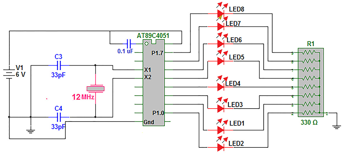
Circuit description:
As shown in figure circuit is built using micro controller AT89C4051, 8 RED LEDs and few other components.
· 8 RED LEDs are connected to port P1 in current sourcing configuration. Their cathodes are connected ground through resistor network (8 pack) of 330Ω each. The LED will be turned ON when port pin is high (1)
· A crystal of 12 MHz along with two 33 pF capacitor is connected to crystal input pins X1 and X2 (4 & 5). It provides required clock signal to micro controller for its all internal operations
· A 0.1 uF capacitor is connected between Vcc supply and reset pin (1). It gives power on reset pulse to micro controller and resets it when supply is given
· Circuit is given power supply through 6 V battery
Assembly and mounting arrangements:

Fig. 1: Block Diagram of 8051 Microcontroller based Propeller LED Pattern Generator
The circuit along with battery has to rotate to create different patterns (visual effects). To generate persistence of vision the circuit is rotated at very high RPM using single phase AC motor. The AC motor used here is the motor taken out from hand blander that has very high RPM. Its RPM are controlled by conventional fan regulator. First the motor is housed in wooden box using screws and then the box is rigidly fixed on stone base using nut-bolts so that motor can not vibrate at high or low RPM. The circuit is mounted on shaft of motor directly using nut-bolt. As shown in figure the circuit is not fixed from the centre to the shaft but it has longer span on one side and shorter at other side. This is done to counter balance battery weight with other circuit components. This is required to stop wobbling of entire assembly.
Working and operation
When supply is given to circuit all the LEDs will start blinking (but you can not see any pattern as it can be visible when circuits starts rotating). Next switch on AC supply for motor so that it will start rotating. As soon as motor attains particular speed different patterns will be visible due to principle of persistence of vision. Let us see how different patterns are generated
Pattern 1: when all LEDs are on and off with delay (in mili seconds*) in between the pattern will be like this

Fig. 2: Representation Image of Propeller LED Pattern 1
* The delay has to be adjusted by trial and error as per the speed of motor to get the pattern visible. The delay has to be adjusted for following patterns also
Pattern 2: alternatively make first 4 LEDs ON and last 4 LEDs OFF and vice versa with delay in between. It will generate following pattern
Fig. 3: Representation Image of Propeller LED Pattern 2
Pattern 3: one by one turn ON two LEDs at a time like first 1 & 2, then 3 & 4, then 5 & 6 and last 7 & 8 with delay and repeat it continuously. It generates following pattern (like Indian holy symbol SWASTIK

Pattern 4: with slight modification in above pattern after going from 1-2, 3-4, 5-6, 7-8, return in reverse order as 7-8, 5-6, 3-4, 1-2. This will make following pattern like dumbbell shape)
Fig. 5: Representation Image of Propeller LED Pattern 4
Pattern 5: one by one turn ON only one LED at a time from 1 to 4 and then 4 to 1. It generates following pattern like flower (or butterfly)
Fig. 6: Representation Image of Propeller LED Pattern 5
This is how you can make so many different patterns by changing sequence for LED blinking.
All these above patterns are generated by micro controller with the help of program loaded into its internal EEPROM. The program sends different data to port P1 with some delay in mili second that will turn ON / OFF LEDs and that creates above different patterns when motor rotates.
Software logic and program
The program generates 7 different patterns by generating 7 different chasing effect on LEDs. It automatically alters the effect after every 10 second. It continuously runs the timer. The timer expires after every 50 ms and generates interrupt. So the program counts 200 such interrupts that means 200×50 ms = 10000 ms = 10 sec. when program counts 200 interrupts, it sets new_pattern_flag – that means the pattern should be now changed. Then it enters into continuous loop and before that it again clears new_pattern_flag. It remains into continuous loop and generates pattern till again new_pattern_flag sets after 10 second. One by one the program changes 7 patterns after every 10 second so total of 70 second (1 minute and 10 second) and again it starts from 1st pattern and repeat all 7 patterns continuously.
Here is the program that is written in C language. The program is compiled using KEIL (IDE) software tool for generic 8051 micro controllers. When the program is compiled it generates HEX file. This HEX file is loaded into internal EEPROM of AT89C4051 micro controller using EEPROM programmer software and hardware tools.
Project Source Code
###
#include
unsigned int count=1,timer_int_count=0,new_pattern_flag;
////////////////////////////// delay in mili second /////////////////////////
void delay()
{
unsigned int i;
for(i=0;i<775;i++);
}
//////////////// generate pattern 1 /////////////////////////////////////////
void pattern1()
{
unsigned int x;
while(new_pattern_flag==0)
{
P1 = 0x01; // turn ON only 1 LED at a time
delay();
for(x=0;x<7;x++)
{
P1 = P1<<1; // shift it left from 1 to 8
delay();
}
}
}
///////////////////// generate pattern 2 ////////////////////////////////////
void pattern2()
{
unsigned int x;
while(new_pattern_flag==0)
{
P1 = 0x03; // turn ON 2 LEDs at a time
delay();
for(x=0;x<3;x++) // shift left
{
P1 = P1<<1;
delay();
}
}
}
/////////////////////// generate pattern 3 //////////////////////////////////
void pattern3()
{
while(new_pattern_flag==0)
{
P1 = 0xF0; // upper 4 LEDs ON
delay();
P1 = 0x0F; // lower 4 LEDs ON
delay();
}
}
void pattern4()
{
while(new_pattern_flag==0)
{
P1 = 0x55; // LEDs 1-3-5-7 ON
delay();
P1 = 0xAA; // LEDs 2-4-6-8 ON
delay();
}
}
void pattern5()
{
while(new_pattern_flag==0)
{
P1 = 0xFF; // all LEDs ON
delay();
P1 = 0x00; // all LEDs OFF
delay();
}
}
void pattern6()
{
unsigned int x;
while(new_pattern_flag==0)
{
P1 = 0x01; // one by one turn ON LEDs
delay();
for(x=0;x<7;x++)
{
P1 = P1<<1; // and shift left
delay();
}
P1 = 0x80; // one by one turn ON LEDs
for(x=0;x<7;x++)
{
P1 = P1>>1; // and shift right (in reverse)
delay();
}
}
}
void pattern7()
{
unsigned int x;
while(new_pattern_flag==0)
{
P1 = 0x03; // turn ON 2 LEDs and
delay();
for(x=0;x<3;x++)
{
P1 = P1<<1; // shift left
delay();
}
P1 = 0xC0; // turn ON 2 LEDs and
for(x=0;x<3;x++)
{
P1 = P1>>1; // shift right (reverse)
delay();
}
}
}
////////////////////// timer ISR ////////////////////////////////////////////
void timer0_int() interrupt 1
{
timer_int_count++; // increment interrupt count
if(timer_int_count == 200) // if its 200
{
count++; // increment pattern count
timer_int_count = 0; // reset interrupt count
new_pattern_flag=1; // and set the flag
}
TH0=0x3C; // re initialize timer
TL0=0xAF;
}
//////////////////////////// main function //////////////////////////////////
void main()
{
P1 = 0x00; // P1 as output port
TMOD = 0x01; // Timer 0 as 16 bit timer
TH0=0x3C; // load initial value
TL0=0xAF;
IE = 0x82; // enable timer 0 overflow interrupt
TR0=1; // start timer
while(1) // generate pattern as per pattern count
{ // value from 1 to 7
if(count==1) {new_pattern_flag=0;pattern1();}
else if(count==2) {new_pattern_flag=0;pattern2();}
else if(count==3) {new_pattern_flag=0;pattern3();}
else if(count==4) {new_pattern_flag=0;pattern4();}
else if(count==5) {new_pattern_flag=0;pattern5();}
else if(count==6) {new_pattern_flag=0;pattern6();}
else if(count==7) {new_pattern_flag=0;count=0;pattern7();}
}
}###
Circuit Diagrams
Project Video
Filed Under: Electronic Projects
Filed Under: Electronic Projects

Questions related to this article?
👉Ask and discuss on Electro-Tech-Online.com and EDAboard.com forums.
Tell Us What You Think!!
You must be logged in to post a comment.