The post explains about how to use stm32 pins as input using keil and stmcubemx ide. A simple led on/off tutorial with push button as input is made to explain the coding and working. When a push button is pressed the led turns on and when push button is released the led turns off. The project is pretty straight forward. Before beginning the tutorial i would recommend to take the tutorial on getting started with stm32f103 microcontroller, keil ide and stumcubemx code initialize. This will introduce you how to initialize/configure and align the stmcubemx and keil ide to start working with stm32f103 microcontrollers. You wont understand this project if you dint’ have introduction to stmcubemx and keil ide.
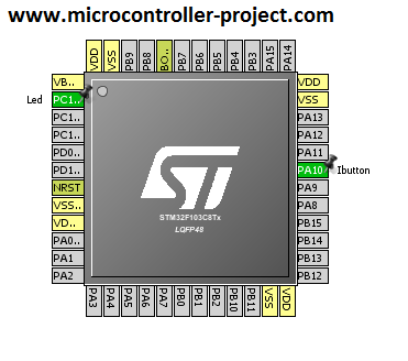
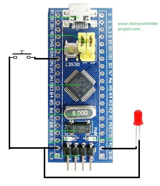
The circuit of the project is pretty straight forward. I connected the led to pin#pc-13 of stm32f103c8t6 and button to pin#pa-10.
|
Stm32f103 led and button pins declaration in stmcubemx
|
stm32f103 gpios as input/output and pull-up/pull-down resistors configuration
The Led pin Pc-13 is declared as output and button Pa-10 as input. Pa-10 pin as an internal pull up resistor. I enabled it and connected my button directly to ground. In the upper picture you can see that GPIO PA10 is in Input Mode and PC-13 in Output Push Pull Mode. Initial output level at PC-13 led pin is declared as high. Output frequency for Led pin set to medium. If you did not understand any thing at this level please take the tutorial mentioned above. It explains all this stuff deeply.
|

|
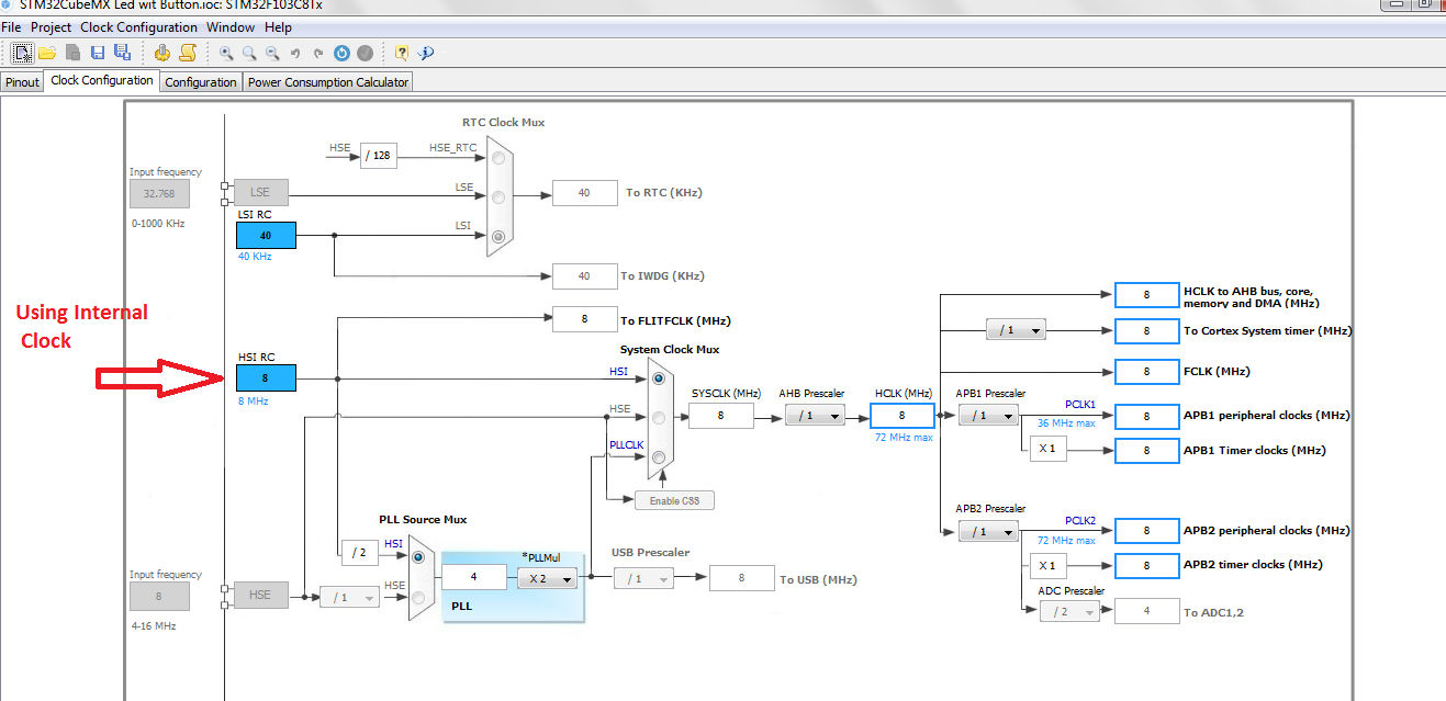
Stm32f103 microcontroller supports internal and external clock sources. Internally it has 2 RC oscillators HSI(High speed internal) and LSI(Low speed internal). High speed internal has 8Mhz clock and Low speed internal has 40khz clock. Externally stm32f103 supports HSE(High speed external) and LSE(Low speed external). High speed external supports max 16Mhz input clock and Low speed external supports 1000khz maximum clock. Stm32f103 has an internal PLL circuit from which we can generate clock signal of 72Mhz. We can go above 72Mhz but since stm32 works at max clock of 72Mhz so we did go above 72Mhz. In this tutorial i am using High speed internal clock source 8Mhz. Settings for HSI(High speed internal) are shown below.
|
stm32f103 led with push button circuit diagram
|
After generating the startup initialization code from stmcubemx its time to write our desired logic “Led on/off with push button”. Its a simple code if we write it in c or c++ but in keil it all depends on the syntax supported by the compiler and the drivers/libraries we are using. I am working with Hal drivers released by the stmicroelectronics. These Hal drivers are directly installed in to our pc when we download stmcubemx software package. When we generate code from stmcubemx for keil the necessary hal drivers and libraries are directly copied to the project folder.
The while(1) loop in main() function is where we write our code. I write the below code their for our logic and its working perfectly and according to the desired output.
if(HAL_GPIO_ReadPin(Ibutton_GPIO_Port, Ibutton_Pin)==GPIO_PIN_RESET) //Check if button pressed
HAL_GPIO_WritePin(Led_GPIO_Port, Led_Pin,GPIO_PIN_SET); //If pressed Led Switch On
else
HAL_GPIO_WritePin(Led_GPIO_Port, Led_Pin,GPIO_PIN_RESET); //Else Led Switch Off
HAL_GPIO_ReadPin() function reads the status of the pin and returns the status. It needs 2 parameters to work one the port of the pin and second the pin number. In our case port is Ibutton_GPIO_Port and pin number is Ibutton_Pin.
HAL_GPIO_WritePin() writes to the specified pin. Makes it high or low. It needs 3 parameters port, pin and data. In our case port is Led_GPIO_Port pin is Led_Pin and data is SET/RESET.
- GPIO_PIN_RESET – Write 0 to pin, Makes pin Low
- GPIO_PIN_SET – Write 1 to pin, Makes pin High
Watch the project video….
You may also like:


Filed Under: Electronic Projects, STM32, STM32.

Questions related to this article?
👉Ask and discuss on Electro-Tech-Online.com and EDAboard.com forums.
Tell Us What You Think!!
You must be logged in to post a comment.