PWM or Pulse Width Modulation is the technology to generate a steady output voltage from inverters. When compared to the conventional Semi Sine wave and Pure sine wave inverters, PWM Inverter offers superior quality. PWM Inverters use MOSFET technology at the output stage, so that any type of loads can be connected to the inverter. These inverters also have voltage control and load protection circuits.
Pulse Width Modulation
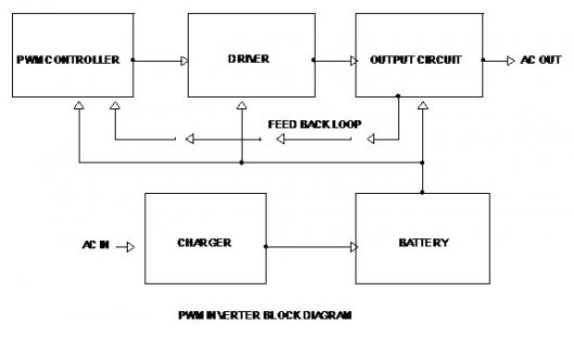
In a standard Inverter without the PWM technology, the output voltage changes according to the power consumption of the load. The PWM technology corrects the output voltage according to the value of the load by changing the Width of the switching frequency in the oscillator section. As a result of this, the AC voltage from the Inverter changes depending on the width of the switching pulse. To achieve this effect, the PWM Inverter has a PWM controller IC which takes a part of output through a feedback loop. The PWM controller in the Inverter will makes corrections in the pulse width of the switching pulse based on the feedback voltage. This will cancel the changes in the output voltage and the Inverter will give a steady output voltage irrespective of the load characteristics.
PWM Inverter Technology
To design an Inverter, many power circuit topologies and voltage control methods are used. The most important aspect of the Inverter technology is the output waveform. To filter the waveform (Square wave, quasi sine wave or Sine wave) capacitors and inductors are used. Low pass filters, are used to reduce the harmonic components. Resonant filter can be used if the Inverter has a fixed output frequency. If the inverter has adjustable output frequency, the filter must be tuned to a level above the maximum fundamental frequency. Feedback rectifiers are used to bleed the peak inductive load current when the switch turns off.
As per the Fourier analysis, a square wave contains odd harmonics like third, fifth, seventh etc only if it is anti-symmetrical about 180 degree point. If the waveform has steps of certain width and heights, the additional harmonics will be cancelled. If a Zero voltage step is introduced between the positive and negative parts of the square wave, the harmonics that are divisible by three can be eliminated. The width of the pulse should be 1/3 of the period for each positive and negative steps and 1/6 of the period for each of the Zero voltage steps. This leaves on the fifth, seventh, eleventh, thirteenth harmonics etc.
The Pulse Width Modulation technology is meant for changing the characteristics of the square wave. The switching pulses are Modulating, and regulating before supplied to the load. When the Inverter requires no voltage control, fixed pulse width can be used.
In order to increase the efficiency of the PWM inverter, the electronic circuit is highly sophisticated with battery charge sensor, AC mains sensor, Soft start facility, output control etc. The PWM controller circuit uses PWM IC KA 3225 or LM 494 .These ICs have internal circuits for the entire operation of the pulse width modulation. The Oscillator circuit to generate the switching frequency is also incorporated in the IC. Output driver section uses Transistors or Driver IC to drive the output according to the switching frequency. Output section uses an array of Switching MOSFETs to drive the primary of the stepping transformer. Output voltage is available in the secondary of the stepping transformer.
Filed Under: Electronic Projects

Questions related to this article?
👉Ask and discuss on EDAboard.com and Electro-Tech-Online.com forums.
Tell Us What You Think!!
You must be logged in to post a comment.