A random number generation is very important in computing devices which helps them to do task in random manner. The applications of random number generation can be found in shuffling the audio files in an audio player, in almost all kind of digital games, generating passwords etc.There are so many algorithms which can generate the random numbers. The random number generating algorithms differ from other algorithms in an interesting way; they actually reads a random number from the hardware like the noise from the unconnected pins and then apply some calculations on it to generate a number which is inside a specified range.
This particular project explains how to generate a random number with the help of an Arduino board. The Arduino is an easy prototyping platform which is popular among both the hobbyist and experts due to its simplicity, ability and also due to the help available from the internet. The Arduino board is basically an AVR based board including all the required hardware for the microcontroller to function properly and also is flashed with the Arduino boot-loader. All the Arduino boards are compatible with the Arduino IDE which helps to compile the code and to program the board.
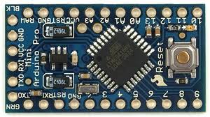
This particular project uses the Arduino pro-mini board which has a very small size and can be connected with bread board compatible connectors. The board comes with either ATMEGA128 or ATMEGA328 controller inside it which operates with a crystal frequency of 8MHz or 16MHz. The Arduino pro-mini board has digital pins marked as 2, 3, 4 up to 13. In an Arduino board some of the digital pins can be configured as analog output pins and there are also dedicated analog input pins which can be used for voltage sensing applications.
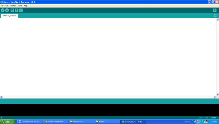
The image of the arduino pro-mini board and the arduino IDE are shown below;
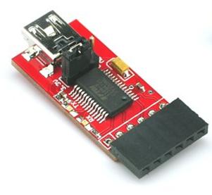
Since the arduino pro-mini board has no circuitary for interfacing it with the serial port or the USB port of the PC, an external USB to TTL converter board is required to connect it with the PC. This hardware helps in programming the arduino board and also helps in the serial communication with the USB port of the PC.
It is assumed that the reader has gone through the project how to get started with the arduino and tried out all the things discussed there.The Arduino pro-mini board has 8 analog input pins marked as A0, A1 up to A7. They are actually the input channels to the built-in ADC of the ATMEGA328 which can read the analog value and convert them to the digital equivalent. In normal analog voltage sensing applications the required analog input pin will be connected to a voltage which needs to be read. Suppose the situation in which the analog pin is left unconnected. The voltage at the pin is undefined and hence when read using the ADC the digital output will also be an undefined random value. This is the basic method by which a random number is obtained.
The first random number obtained from the hardware is called a ‘random seed’. This random seed is then applied to algorithms called random number generating algorithm which can generate a random number which inside a specified range. There are built-in functions in the Arduino IDE which helps in generating random numbers. This particular project makes use of two functions namely randomSeed() and random() and the details of the function are discussed below;
randomSeed()
randomSeed() initializes the pseudo-random number generator, causing it to start at an arbitrary point in its random sequence. This function has a parameter which decides from which point in the sequence should the random number generation starts. To initialize the pseudo-random number generator with a new sequence each and every time, the value provided as the parameter should also be different.
This particular code reads a random value from the analog input pin A0 which is left unconnected so that each and every time the code runs it can generate different set of random numbers.
random()
The function random() is used to generate pseudo-random number which falls in a specified range. The function is always called after calling the randomSeed() function. This function has two parameters of which the first one is the lowest required value and the second one is the largest required value.
THE CODE
The code written for this project initializes pseudo-random number generator with a random value read from the analog input pin A0 and uses the function randomSeed(). The function used to read the value from A0 is analogRead() function which is already discussed in the previous projects on how to use analog input and analog output of Arduino board, how to use Arduino to display sensor values, how to make dynamic sensor display using Arduino, how to save sensor values in the EEPROM of the Arduino.
The function random() is then used to generate a pseudo-random number and is send to the Serial monitor window with the help of the functions Serial.begin() and Serial.write() which are already discussed in previous projects on how to do serial communication with the Arduino, how to send and receive serial data using arduino, how to do serial debugging with the Arduino. The code also glows an LED using the same random number to vary its brightness by writing the same value to the analog output pin where the LED is connected.
When the coding is finished one can verify and upload the code to the Arduino board as explained in the project how to get started with the Arduino. The code will continuously generate random numbers and one can observe them with the help of Serial monitor as explained in the project on how to do serial debugging with the Arduino.
Project Source Code
###
/*============================ EG LABS ===================================//Demonstration on how to use 16x2 LCD display with an arduino board* LED anode attached to digital output 6* LED cathode attached to ground through a 1K resistor//============================ EG LABS ===================================*/// include the library code:#include <LiquidCrystal.h>// initialize the library with the numbers of the interface pinsLiquidCrystal lcd(12, 11, 5, 4, 3, 2);long randNumber; // the variable which is supposed to hold the random numberconst int analogOutPin = 6; // Analog output pin where the LED is attached tovoid setup(){// set up the LCD's number of columns and rows:lcd.begin(16, 2);// Print a message to the LCD.lcd.print("ENGINEERS GARAGE");lcd.setCursor(0, 1);lcd.print(" RANDOM NUMBER ");// initialize the serial portSerial.begin(9600);// initialize the pseudo-random number generatorrandomSeed(analogRead(0));}void loop(){randNumber = random(0, 255); // generate a random numberSerial.println(randNumber); // send the random number to the serial portanalogWrite(analogOutPin, randNumber); // vary the brightness of the LED according to the random numberdelay(300);}###
Circuit Diagrams

Project Components
Project Video
Filed Under: Arduino
Filed Under: Arduino

Questions related to this article?
👉Ask and discuss on Electro-Tech-Online.com and EDAboard.com forums.
Tell Us What You Think!!
You must be logged in to post a comment.