Random Number Generator with NRF24LE1
Random number sometimes plays an important role in our life. Think of a lottery ticket you have purchased. Now what if a random number taken out of lottery lot matches your ticket number? We will be glad if that happens. Random number generators are also used in making games more puzzling and non-deterministic. Do you know microcontrollers too can generate random number? Today we are going to discuss an interesting feature of NRF24LE1 which is Random Number Generator (RNG).
The NRF24LE1 contains a thermal noise based Random Number Generator which produces non-deterministic sequence. For making it more powerful and random we can use a digital corrector algorithm which removes any bias towards 0 or 1. This is also an inbuilt feature. RNG generates an 8-bit number which is stored in 8-bit register. So the range of number will be 0 – 255.
Some features of RNG are:
• Number generation rate up to 10 kilobytes per second
• Non-repeating sequence
• Works even when NRF is in standby mode
• No initial input vale required for generation (Self generation)
• Thermal noise based non-deterministic architecture
The RNG is controlled by two registers:
1. RNGCTL (Random Number Generator Control) register- It is an 8-bit register. The purpose of various bits are:
• Bit 7 – used to power up RNG
• Bit 6 – used to enable bias corrector
• Bit 5 – generation completed flag. 1 : Data Ready
• Bit 4:0 – not used
2. RNGDAT (Random Number Generator Data) register – It is an 8-bit register which sores the generated number.

Fig. 1: Prototype of NRF24LE1 Module based Random Number Generator
We will now cover the process of RNG in simple steps.
• First we have to start the generator. For that we have to write 1 to bit 7 of RNGCTL.
• If we want to enable bias corrector we can write 1 to bit 6 of RNGCTL.
• We can check if the number has been generated by reading bit 5 RNGCTL. An interrupt RNGIRQ is also produced after successful generation. It takes about 0.1 mS to generate a number when bias corrector is disabled and four times as long when corrector is enabled. Also it takes about 0.25 ms for the first time generation after RNG is powered up.
• The generated one byte data can be accessed through RNGDAT register.
We can also use functions provided by Nordic libraries:

Fig. 2: Table Listing Functions of NRF24LE1 Wireless Module
Function Input Parameter Output Description
hal_rng_power_up() 0/1 – To power the RNG
0:OFF
1:ON
hal_rng_bias_corr_enable() 0/1 – To use bias corrector
0:Disable
1:Enable
hal_rng_read() – 8-bit data To read the generated number
hal_rng_data_ready() – 0/1 To check the status of RNG
0:Data not ready
1:Data ready

Fig. 3: Image of NRF24LE1 Module based Random Number Generator
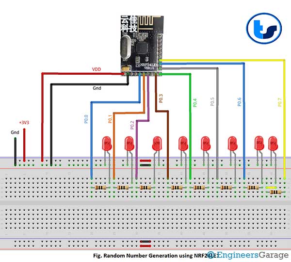
We have written a code to make users understand its working. The generated 1 byte number has been output to Port0 where LEDs are connected. As the number generated is random, these LEDs will blink in a random fashion.
You may also like:


Project Source Code
###
//Program to#include"reg24le1.h" // I/O header file for NRF24LE1
#include"hal_delay.h" // header file containing delay functions// main functionvoid main(){RNGCTL = 0xC0; // enable random number generatorP0DIR = 0; // Port 0 as output// infinite loopwhile(1){while(!(RNGCTL & 0x20)); // check if random number is generated or notP0 = RNGDAT; // output the number to Port 0delay_ms(500); // delay of 500 ms}}###
Circuit Diagrams
Project Video
Filed Under: Tutorials
Filed Under: Tutorials

Questions related to this article?
👉Ask and discuss on EDAboard.com and Electro-Tech-Online.com forums.
Tell Us What You Think!!
You must be logged in to post a comment.