In the previous tutorial, we discussed serial communication protocols available on Raspberry Pi. We discussed the terminology of data communication and defined the terms like ‘port’, ‘bus’, ‘interface’, ‘protocol’ and ‘standard’. We talked about UARTs on Raspberry Pi and how these UARTs are referenced by different serial Linux device names when they are accessed through different interfaces and ports of Raspberry Pi. The serial port of Raspberry Pi is the most useful interface when it comes about communicating with embedded electronics. In this tutorial, we will discuss about implementing serial UART communication using Raspberry Pi’s serial port. We will, then, use this to setup bi-directional communication between Raspberry Pi and a Personal Computer (PC).
UART protocol
In embedded electronics, interlinking circuits to exchange data is most important. This data communication is usually done through serial communication. There are hundreds of serial communication protocols and all these protocols require at least one but never more than four wires to exchange data. UART protocol is the most common serial communication protocol that is widely used across all platforms (general-purpose computers, embedded electronics, networking etc). It is one communication protocol that you may find essentially on any device. UART is so common that whenever techies say ‘Serial’, it actually means UART.
UART is basically a serial communication protocol. To enable serial communication using this protocol, a circuit called Universal Asynchronous Receiver/Transmitter (UART) is required. UARTs as standalone ICs are also available. However, UARTs are mostly integrated inside microcontroller chips and embedded processors. Like, the Raspberry Pi 3B has two UARTs and 4B has 6 UARTs on their Broadcom SoCs. Most of the Arduino boards have only one UART.
Many microcontrollers and embedded processors are also capable of implementing software UART. In this case, they do not have actual UART circuit integrated or employed for serial communication, instead they mimic the protocol by bit-banging. Software UART (Software Serial) is often processor intensive and not as precise as actual UART.
UART is a serial communication protocol, so it actually dictates how data must be encoded and decoded across bus between two devices. It is a asynchronous communication protocol and does not involve use of a clock signal (common) between two devices. It can be implemented as both half-duplex and full-duplex depending upon the interface that uses this protocol. The serial communication on UART is point-to-point (peer) type and requires only two wires on the bus.
UART data encodings
On UART protocol, data is transmitted in packets or frame of bits. The frame/packet consists a data chunk and synchronization bits.
Data Chunk – The bits that are the part of actual data to be shared are called data chunk or data-bits packet. There can be 5 to 9 bits in a data chunk. However, 8 bits or a byte is the common size of data chunk.
Synchronisation Bits – As you know UART does not use clock signals between communicating devices, so some other bits are sent along the actual data chunk to enable synchronization of data. Obviously, these bits are called synchronisation bits. these include start bit, stop bit(s) and parity bit.
- Start Bit – This bit indicates that serial communication has started. This bit is always LOW. Therefore, a HIGH-to-LOW transition indicates the beginning of each data frame/packet. The data chunk follows the start bit.
- Stop Bit(s) – There can be one or two stop bits. The stop bit is always HIGH. It indicates the end of the data packet/frame.
- Parity Bit – Parity checking is a low-level error handling method. The parity bit is an optional stop bit that can be included in the data frame to ensure accuracy of the data chunk. The parity can be even (0) or odd (1). If parity is set to be 0, the sum of the bits of data chunk and parity bit will be 0 if the data packet is transferred without error. If parity is set to be 1, the sum of the bits of data chunk and parity bit will be 0 if the data packet is transferred without error. Using a parity bit slows down slightly the transfer rate but it is the only mechanism for error-handling over UART communication. The parity bit is included in the data frame immediately after the data chunk.
Baud Rate – Baud rate is the data transfer rate between two devices. The two devices communicating data serially must have the same baud rate. It is expressed in bits per second (bps). The common baud rates are 9600 bps, 1200 bps, 2400 bps, 4800 bps, 14400 bps, 19200 bps, 28800 bps, 38400 bps, 57600 bps and 115200 bps. The baud rate also indicates the length of a bit over the bus. For example, if the baud rate is 9600, it means that 9600 bits are transferred over the bus in a second. Therefore, the width of each bit is 104.166 microseconds and accordingly must be the sampling of bits on both devices. Most of the microcontrollers and embedded processors cannot handle a baud rate higher than 115200 bps. If the baud rate is too high compared to the clock which the device (like microcontroller/processor) itself is clocked to, then the data transferred could not be received without error.
Endianness – Endianness refers to the order of bits in data chunk i.e. whether data chunk is transferred from LSB (Least Significant Bit) to MSB (Most Significant Bit) or vice-versa. The data is usually transferred LSB first.
UART voltage levels
UART circuits use two voltage levels – one voltage to indicate bit 0 and other voltage to indicate bit 1. The signal levels indicating 0 and 1 depends upon the device or interface. The 5V TTL devices like Arduino use 0V as bit 0 and 5V as bit 1. The 3.3V TTL devices like Raspberry Pi use 0V as bit 0 and 3.3V as bit 1. Some devices may use 0V as bit 0 and 1.8V as bit 1. RS-232 serial interfaces (ports) use positive and negative voltages in range from -15V to 15V for logical bits. The positive voltage indicates bit 0 and negative voltage indicates bit 1 on RS-232 ports.
When two devices are connected serially, the UART voltage levels must be same. If two devices have different UART voltage levels, a suitable bridge board or adaptor must be used to interconnect them. For example, Raspberry Pi is 3.3V TTL device and Arduino is 5V TTL device. So, to connect both devices serially a suitable 3.3V TTL to 5V TTL adaptor must be used. If serial TTL port of Raspberry Pi is directly connected to serial TTL port of Arduino, it may damage the serial port of the Raspberry Pi. Similarly, if serial TTL port of Raspberry Pi has to connect with RS-232 port (-15V to 15V) of a device, suitable serial-RS-232 converter must be used. If serial TTL port of Raspberry Pi has to connect with USB port (5V) of a device, suitable serial-USB converter must be used.
How UART protocol works
For serial communication over UART protocol, two devices should either have same UART voltage levels or their serial ports must be connected to each other using a suitable bridge board or voltage adaptor. The transmitter of one device connects to receiver of the other device while its receiver connects to the transmitter of the other device. The two devices must decide to communicate data using a common baud rate, data chunk size, and use of parity bit. The UART protocol shared between two devices can be summarized as follow –
<Baud Rate> <Data Bits> <Parity> <Number of Stop Bits>
For example, if two devices decide to communicate over UART protocol configured 9600 8N1, it means both devices will have 9600 bps baud rate; data chunk will have 8 bits; There will be no parity bit; and there is one stop bit. If two devices decide to communicate over UART protocol configured 9600 8E1, it means both devices will have 9600 bps baud rate; data chunk will have 8 bits; There will be even parity; and there is one stop bit. Similarly, 115200 8O2 indicates baud rate is 115200 bps; data chunk has 8 bits; there is odd parity; and there are two stop bits.
The digital signal carrying data over UART protocol may look like as shown in the image below.
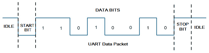
Example of UART signals
Advantages & disadvantages of UART
UART is the most common serial protocol. It needs only two wires for communication between two devices and does not need any clock signal between them. The size of the data chunk can be changed between 5 bits and 9 bits. There is also error-handling available in the form of parity bit. Despite being the most common serial communication protocol, UART is not the perfect data communication solution. It allows data transfer only between two devices. Additional devices cannot be added to share the bus. The maximum size of data chunk is limited to 9 bits while the baud rate cannot practically exceed 115200 bps.
USB-serial boards
USB is now the common interface on general-purpose computers and associated peripherals. RS-232 ports have been completely replaced by USB on desktops and all kinds of portable computers. Raspberry Pi may require to communicate with PCs, Workstations, portable computers or mobile devices in many cases. It can be connected with a desktop/mobile either using USB-to-USB cable, over Ethernet, over Bluetooth, Wi-Fi and even serial TTL port. For enabling serial communication between serial port of Raspberry Pi and a device having USB interface, a USB-Serial board (USB-to-UART converter) is required. This is because USB may have signal voltage levels up to 5V and any device connected to a USB port must identify itself through a device driver on the computer. USB-Serial boards let connect USB interface of a computer with serial TTL port of a microcontroller or embedded computer. The board act as a serial port on the behalf of computer.
The USB-Serial boards have a chip for this purpose. Some of the popular chips are FTDI FT232, Silicon Labs CP2102 and Prolific PL2303. The most important thing to take note while selecting a USB-Serial board is its I/O voltage. For Raspberry Pi, the selected board must support I/O voltage of 3.3V. The USB-to-UART converters can have maximum baud rate from 1Mbps to 12 Mbps and may have I/O serial buffer of 512 bytes or less. FTDIs are the oldest USB-Serial converters available. Most of the USB-Serial boards have built-in drivers on Windows while Linux drivers are available from the Kernel developers instead of the chip manufacturers. Therefore, most of the USB-Serial boards are plug-and-play devices. The USB-Serial adaptors have a USB port and a pin header exposing connections for ground, VCC, Rx, Tx and data control modem lines like RTS, CTS, DTR, DSR, RI and DCD.
Drivers for USB-serial boards
When a USB-Serial board is connected to a computer, if the computer automatically gains a serial port, it means that the board is ready to use as a plug-and-play device. Otherwise, it exclusively requires installing its driver on the desktop.
The Windows usually have built-in driver for these boards or can get one with a Windows Update. MacOS also have built-in drivers for many chips. Alternatively, Serial app for MacOS comes with its own drivers. Linux Kernel 2.6 and above comes with built-in drivers for USB-to-UART converters. If on plugging a board, it is not detected as serial port, the problem may be with drivers. So, try download and install suitable drivers if the USB-to-Serial board is not detected on a desktop system.
Wiring & hardware
If voltage-compatible serial ports of two devices are to be connected, it is pretty straight forward. Connect Tx of one device to Rx of the other and its Rx to the Tx of the other device. The UARTs on two devices may share a common ground or the ground voltage reference should be same on both devices (ideally it should be 0V on both devices). This is applicable when both devices (UARTs on them) have same voltage levels.
If a voltage shifter or adapter is used to connect two devices serially, the connections depend upon the pin configuration of the adaptor. Like on a USB-Serial board, the Tx of Raspberry Pi or a microcontroller must be connected to Tx of the USB-Serial board and Rx of Raspberry Pi or a microcontroller must be connected to Rx of the USB-Serial board. The ground of board must also be essentially connected to the ground pin of Raspberry Pi or the microcontroller. The Rx, Tx and ground pins are essential connections between a USB-Serial board and Raspberry Pi/a microcontroller. It is common mistake that newbie connect Rx of Raspberry Pi/a microcontroller with Tx of USB-Serial board and Tx of Raspberry Pi/a microcontroller with Rx of USB-Serial board in attempt to setup serial communication between desktop and RPi/microcontrollers.
If the board has jumpers for selection of TTL voltages, appropriate voltage level (like 3.3V for Raspberry Pi) must be selected by placing the jumper in right slot. Otherwise, the board may have a VCC pin which should be connected to right supply voltage, like to 3.3 V for Raspberry Pi.
Finding serial port name on desktop
Once the USB-Serial board is connected to a computer, it must be identified as a serial port. Before using a serial application to start talking with Raspberry Pi or a microcontroller from your computer, you need to know the serial port name of your desktop. Many serial applications auto detect the serial port. However, if the application does not have this feature, it is possible to manually know the serial port name.
On macOS, USB-Serial boards appear with device names like /dev/tty.wchusbserial* where * may be any number. The list of connected devices can be populated by executing command sudo dmesg. Alternatively, USB devices can be listed using command ioreg -p IOUSB.
On windows, USB-Serial boards have device names like COM* where * is any number. The device name can be known by device manager. Open device manager by pressing Windows+R and running devmgmt.msc. In the device manager, look for devices listed under Ports tab.
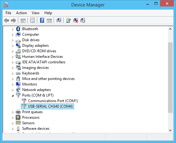
Example of finding serial COM port on Windows
On Linux systems, USB-Serial boards have device names like /dev/ttyUSB* where * is any number. Note that USB-Serial adaptors identify themselves as software-only USB stack devices. The list of USB devices can be populated using command ls /dev/ttyUSB or just ls /dev/. Alternatively, the device name can be found in the log by using command sudo dmesg.
Finding serial port name on Raspberry Pi
In the previous tutorial, we have discussed Linux device names of Raspberry Pi’s UARTs when they are accessed from different interfaces and ports of it. The Linux device names for Raspberry Pi’s UARTs are summarized in the following table:
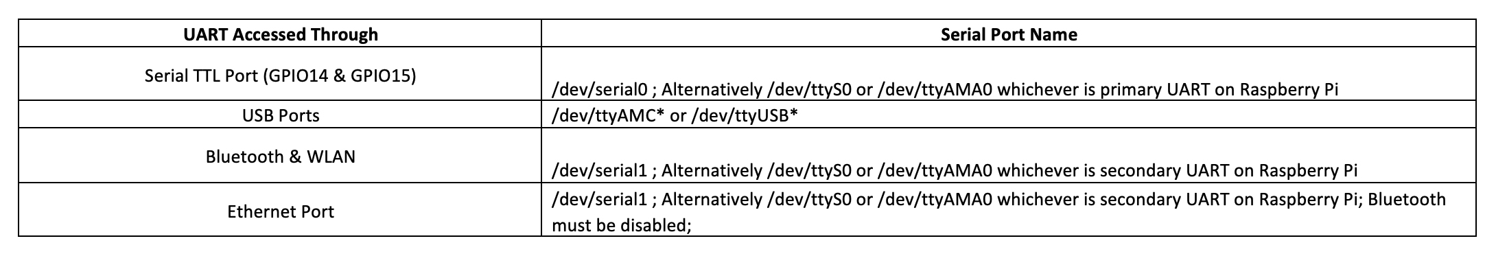
The USB-to-Serial boards connect to serial TTL port of Raspberry Pi. Therefore, /dev/serial0 otherwise /dev/ttyS0 or /dev/ttyAMA0 whichever is primary UART on the respective Raspberry Pi model should be pointed as serial port. If Raspberry Pi is directly connected to a computer using USB-to-USB cable, it may identify the computer’s USB connection as /dev/ttyAMC*.
Serial desktop applications
There are many serial applications available for different desktop systems. You can use tio on Linux; Putty, Termite, RealTerm, KiTTY, Tera Term, or SmarTTY on Windows; Serial on macOS. These applications can be used to exchange text messages over UART protocol.
Hacking embedded devices using UART
UART is one serial port that is essentially on any embedded device. Most of the embedded devices definitely have a UART header on their PCB. This port has access to root shell of the device and is used for console output and accepting commands over UART protocol. Therefore, UART header can be used to hack any embedded device.
The UART header usually have four or five connections having essentially connections for ground, VCC, Rx and Tx. Sometimes, there may not be a header but holes left for UART connections. Try to figure out ground pin and a pin that suspects to be Tx. Measure the voltage at suspected Tx pin with respect to ground pin. It may be 3.3V, 5V or RS-232 voltage level in idle condition. When you boot the device, if the suspected pin is Tx and is transmitting console data, voltage at the pin will drop slightly. The pin may not necessarily using UART protocol, it can also be communicating over I2C or SPI. However, this can be confirmed only by observing the signals from the pin on a logic analyzer or oscilloscope. Alternatively, the pin can be tried with a USB-to-Serial board, if it is detected as a serial port on a serial application, it is a UART’s Tx.
Once you have identified the header as UART port, you only need to connect Rx to Tx, Tx to Rx and Ground to Ground. The VCC pin of the header may be connected to the VCC of USB-Serial bridge but a resistor must be connected in series for protection.
Now, detect the baud rate and try to figure out the UART protocol i.e. number of bits in data chunk, presence of parity bit and number of stop bits. The baud rate can be detected by observing the shortest pulse of signal on an oscilloscope or by using an autobaud program. You may need to observe signals from the UART header of the device on a logic analyzer, CRO or DSO for decoding the protocol. Once the protocol is known, you can hack the embedded device with a Raspberry Pi or a microcontroller. You can also use a serial app on your desktop and connect to the UART header of the embedded device using a USB-to-Serial board to hack the device.
In the next tutorial, we will discuss about serialpi library and use serial TTL port of Raspberry Pi to communicate with a computer.
Filed Under: Raspberry pi

Questions related to this article?
👉Ask and discuss on Electro-Tech-Online.com and EDAboard.com forums.
Tell Us What You Think!!
You must be logged in to post a comment.