In the previous tutorial, we covered TTK menus, layout management in the Tk GUI toolkit, and mouse and keyboard events in Tkinter/TTK. We also discussed multi-threading in Python and created our own class of a threading package.
This means we can implement our Raspberry Pi (RPi) codes exactly as if they are running on a microcontroller. We modified the threading class so that we could kill threads whenever required. Now, it’s time to start using electronics with RPi.
The first recipe that we’re going to implement is an LED driver. We’ll implement our RPi recipes through GUI apps so that we can demonstrate how flexible and powerful controlling embedded electronics from a single-board computer is compared to a microcontroller or microcontroller board. So, our RPi-based GUI will control LED drivers.
RPi vs. microcontrollers
Any embedded controller can interface and communicate with external electronics in five ways:
1. Digital output. The controller may output a digital HIGH or LOW signal to the other device. The voltage levels of the digital signal may be CMOS or TTL logic compatible.
2. Digital input. The controller may read a digital LOW or HIGH signal from the other device. The voltage levels can also be CMOS or TTL logic compatible.
3. Analog output. The controller may output an analog signal to the other device. Typically, this analog signal is not analog but a Pulse Width Modulated (PWM) signal that approximates to analog voltage levels.
4. Analog input. The controller may have built-in Analog-to-Digital (ADC) channels to sense analog voltage levels and convert them into a digital reading.
5. Serial communication. The controller may be capable of communicating with other devices via different serial communication protocols, such as UART/USART (for peer-to-peer communication), I2C/TWI (for half-duplex master-slave serial data communication with multiple devices), or SPI (for full-duplex serial data communication with multiple devices). Other serial communication protocols may be peer-to-peer, half-duplex, or full-duplex.
Most of the microcontrollers are equipped with all the five ways of data and signal communication and may have additional hardware features, such as timers/counters, hardware interrupts, and a real-time clock (RTC).
RPi offers four out of these five signal communication methods and is incapable of analog input. It can perform digital output, digital input, analog output, and communicate via the common serial communication protocols, including USART, I2C, and SPI. It doesn’t have built-in analog-to-digital (ADC) channels.
For analog to digital conversion, RPi must be interfaced with an external ADC that can communicate digital readings to it via serial communication. RPi also has a system timer and an ARM timer that can be used as a typical timer/counter. All of its general-purpose input/output (GPIO) pins can be configured as an interrupt source.
Apart from these controllers-specific features, Raspberry Pi also has USB ports, Ethernet, Wi-Fi, Bluetooth, onboard GPU, HDMI port(s), analog video, audio output, CSI port, and DSI port. It comes with RAM up to 4 GB and a MicroSD card up to 64 GB can be used for booting it.
All of this, combined with the ability to run an operating system (where apps can be programmed in any high-level language), makes the Raspberry Pi a resourceful embedded controller. This single-board computer can also be used for advanced embedded applications that may never run on a microcontroller.
RPi GPIO
One of the most powerful features RPi offers is its GPIO pins arranged as a 40-pin expansion header (or a 26-pin in models before the Pi 1 Model B+) on the top of the board. This GPIO row means it’s able to interface directly with electronics and act as an embedded controller.
Typical desktop computers do not have such GPIO headers and are unable to operate as embedded computers. The only way typical desktop systems can be used as embedded controllers/computers is using USB-to-GPIO, Bluetooth GPIO, or Wi-Fi GPIO modules.
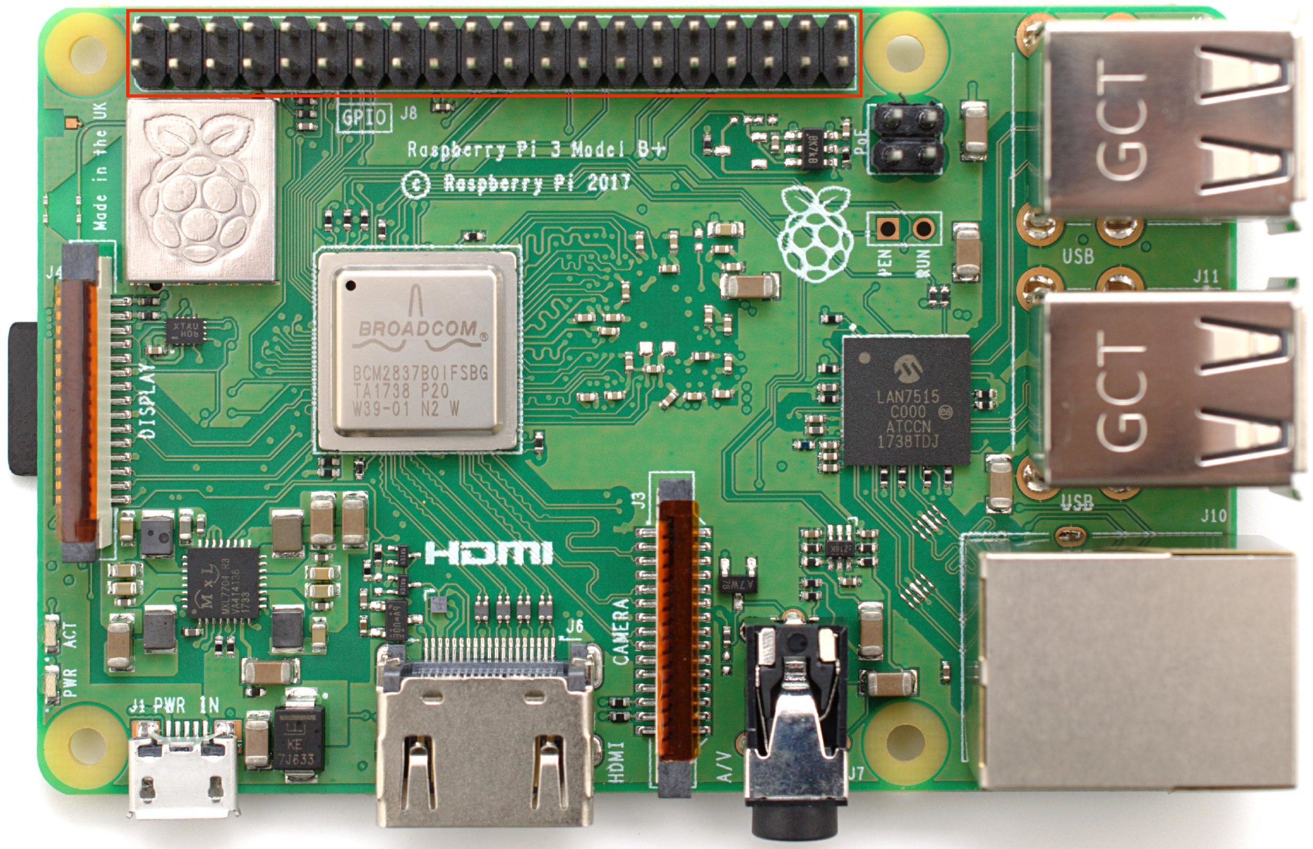
A Raspberry Pi GPIO expansion header.
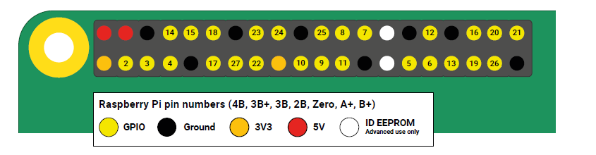
Raspberry Pi board numbers generally refer to the GPIO pins. These are pin numbers on RPI’s P1 header that remain the same for all available models. Counting the pins by starting at the edge of the board, as shown in this pinout diagram…

Raspberry Pi GPIO Pin diagram
Note: not all of the pins are the same. Some are reserved while others offer additional features. The following figure shows the GPIO header’s reserved pins.
Example of Reserved Pins of Raspberry Pi GPIO header
Out of the 40 pins:
- Two pins are connected to Pi’s 5V rail and are reserved to provide a consistent +5.0V DC supply
- Two pins are connected to the Pi’s 3.3V rail and are reserved to provide a consistent +3.3V DC supply
- Eight pins are connected to Pi’s ground and are reserved to provide the common ground
- Two pins are reserved for I2C communication with the HATS EEPROM
- Twenty-six pins are left available for digital input/output and are 3V3 pins (i.e., their outputs can be set to 3.3V and their inputs are 3.3V tolerable)
The pins can be configured to use built-in, pull-up or pull-down resistors except for the GPIO2 (Board Pin Number 3) and GPIO3 (Board Pin Number 5), which have fixed pull-up resistors. The GPIO pins output 3.3V for logical HIGH and 0V for logical LOW. They read 3.3V as logical HIGH and 0V as logical LOW.
All of the 26 GPIO pins can generate software PWM signals. Hardware PWM signals are only available at the:
- GPIO12 (Board Pin Number 32)
- GPIO13 (Board Pin Number 33)
- GPIO18 (Board Pin Number 12)
- GPIO19 (Board Pin Number 35)
For serial communication (USART), the GPIO14 (Board Pin Number 8) is used as a serial transmitter (Tx) and the GPIO15 (Board Pin Number 10) is used as a serial receiver (Rx).
For I2C communication with the Pi HATS (Hardware Attached on Top) EEPROM, the GPIO0 (Board Pin Number 27) is reserved for data and the GPIO1 (Board Pin Number 28) is reserved for the clock signal. For I2C communication with external devices, the GPIO2 (Board Pin Number 3) is used for data, and GPIO3 (Board Pin Number 5) is used for clock signals.
For SPI communication, there are two channels. SPI0 uses the:
- GPIO10 (Board Pin Number 19) for MOSI
- GPIO9 (Board Pin Number 21) for MISO
- GPIO11 (Board Pin Number 23) for SCLK
- GPIO8 (Board Pin Number 24) for CE0
- GPIO7 (Board Pin Number 26) for CE1
SPI1 uses the:
- GPIO20 (Board Pin Number 38) for MOSI
- GPIO19 (Board Pin Number 35) for MISO
- GPIO21 (Board Pin Number 40) for SCLK
- GPIO18 (Board Pin Number 12) for CE0
- GPIO17 (Board Pin Number 11) for CE1
- GPIO16 (Board Pin Number 36) for CE2
Using RPi’s GPIO from Python
For controlling Raspberry Pi’s GPIO pins from Python, first to import the RPi.GPIO module as follows:
import RPi.GPIO as GPIO
The module references IO pins in two ways: as board numbers and as BCM numbers. The board numbers are the pin numbers on RPi’s P1 header. These numbers remain the same for all of the RPi models. The BCM numbers refer to the channel numbers on the Broadcom SoC. Different RPi models may have channel numbers wired to the RPi board numbers.
So, if you use the BCM numbers, it’s necessary to work with the correct schematic for the board you’re using. Otherwise, it’s possible that your script may work on one model but may break on the other.
The numbering system of the pins can be set using the setmode() method of the GPIO module. Here are valid examples of setting a numbering system of IO pins in the Python script:
GPIO.setmode(GPIO.BOARD)
or
GPIO.setmode(GPIO.BCM)
To detect the numbering system of the IO pins, the getmode() method of the GPIO module can be called as follows:
mode = GPIO.getmode()
or
print(GPIO.getmode())
The method returns GPIO.BOARD, GPIO.BCM, or NONE as a string (if the numbering system is not set). So, it’s recommended to use a board numbering system so that your Python script could run on all models without breaking.
It’s also possible that more than one script is run in a session. If one script is already using an IO pin and another script is about to run (which also uses the same IO pin), a warning is generated, prompting the user that the channel is already in use.
To ignore such warnings and continue using the IO pin from the current script, the warnings can be set to False using the setwarnings() method of the GPIO module as follows:
GPIO.setwarnings(False)
However, this must be done before setting the numbering system of the pins. When using the pins as digital input or output, they need to be configured using the setup() method of the GPIO module. A pin can be configured as digital output like this:
GPIO.setup(channel, GPIO.OUT)
Here, the channel refers to the pin number referenced using the board or BCM number. An initial value can also be set to output by the pin while configuring it as digital output:
GPIO.setup(channel, GPIO.OUT, initial=GPIO.HIGH)
To set the output from a pin, the output() method of GPIO module is used:
GPIO.output(channel, state)
Here, the state can be “0” or GPIO.LOW, False for logical LOW, “1” or GPIO.HIGH, or True for logical HIGH. To output the digital signal on multiple pins at the same time using a list of channels as an argument, follow this:
gpio_list = [38,40] # also works with tuples
GPIO.output(gpio_list, GPIO.LOW) # sets all to GPIO.LOW
GPIO.output(gpio_list, (GPIO.HIGH, GPIO.LOW)) # sets first HIGH and second LOW
A pin can be configured as digital input like one of these:
GPIO.setup(channel, GPIO.IN)
or
GPIO.setup(channel, GPIO.IN, pull_up_down=GPIO.PUD_UP)
or
GPIO.setup(channel, GPIO.IN, pull_up_down=GPIO.PUD_DOWN)
To read the digital input, the input() method of the GPIO module is used:
GPIO.input(channel)
The state of a pin configured as digital input can be read using a conditional block-like as follows:
if (GPIO.input(channel)):
print(“HIGH”)
else:
print(“LOW”)
At the end of the script, any resources used by it must be cleaned. This includes the IO pins. If the script is terminated without cleaning, the pins remain in use by RPi. If another script tries to access those pins, a warning is generated. It’s particularly important to clean up if the pins have been used as input without the pull-up or pull-down, as such pins can get damaged by shorting.
The channels can be cleaned using the cleanup() method of the GPIO module. The method also clears the numbering system in use:
GPIO.cleanup()
The LED driver
Light-emitting diodes (LEDs) are similar to signal diodes that can emit visible, infrared, or laser light in a forward-bias condition. These are used for decorative purposes or as indicators of mutually exclusive conditions — like if a device is ON or OFF, an option/feature is selected or not selected, or if the device is working or not.
In certain situations, LEDs are blinked to show that an action/event is in process.
LEDs are two-terminal devices that can be switched ON or OFF in a circuit. An LED is switched ON in a forward-bias condition when it starts glowing and switched OFF in a reverse-bias condition when failing to glow.
An LED driver is a circuit that controls the switch of the LEDs. The LEDs are current-controlled devices that only require 12 to 30 mA forward current for their operation. The GPIO pins of any microcontroller or processor can typically source up to 40 mA current for the output of the logical HIGH. They can also sink the same current for the input of the logical HIGH.
This means LEDs can be directly interfaced and controlled by IO pins of CMOS/TTL chips, including Raspberry Pi. To learn more about LEDs and how they are interfaced in a circuit, check out this Arduino tutorial: Arduino Compatible Coding 04.
An RPi-based, GUI-controlled LED driver
Now that we know how to use Raspberry Pi’s GPIO pins for the digital IO and how LEDs are interfaced in a circuit, let’s build an LED driver.
Components required:
1. Raspberry Pi 3/4 Model B x1
2. LED x1
3. A 330-Ohms resistor x1
4. Breadboard x1
5. Male-to-male jumper wires
Circuit connections:
- Connect RPi’s GPIO21 (Board Pin Number 40) with the LED’s anode
- Connect the LED’s cathode with a 330-Ohm series resistor and ground the other terminal of the resistor
- The DC supply voltage and ground can be given to the circuit from RPi’s Pin Number 2 and Pin Number 6, respectively
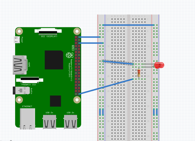
Raspberry Pi LED driver circuit
Circuit diagram
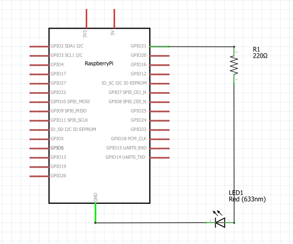
Raspberry Pi LED driver circuit diagram
Programming guide
We aim to control the switching operation of the LED from the GUI. Let’s start from the GUI’s menus, which were developed in the previous tutorial.
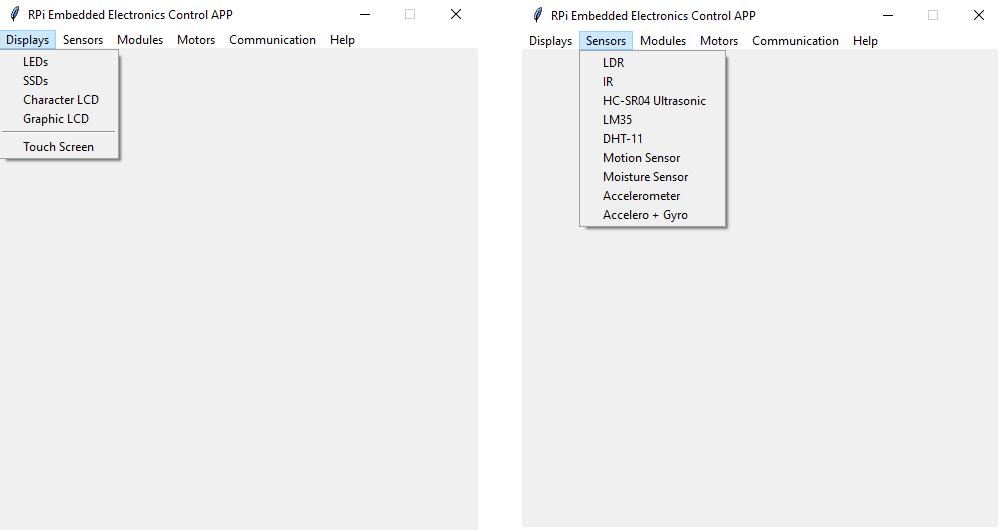
To control the LEDs, we wrote an app that’s loaded when clicking on the “LEDs” menu button in the “Displays” menu. The app runs through the execution of a single function LED_driver().
We assigned the LED_driver() function to the command argument of the add_command() method for the displays_menu, while replacing the donothing() function like this:
displays_menu.add_command(label=”LEDs”, command=LED_driver)
The following modules are imported at the beginning of the script:
from tkinter import *
from tkinter import ttk
import time
import threading
import sys
import RPi.GPIO as GPIO
Since we’ll be running the app as a separate thread so that the GUI does freeze when running the microcontroller-like infinite loop, we declared a global variable to reference this thread.
Global variables are also required to reference the IO pins used in the script. As a single IO pin is used in the script, a variable “gpio_pin” is declared:
thread_LED_driver = None
gpio_pin = 40
Inside the LED_driver() function, our customized threading class is defined. The infinite While loop in the body of the modified run() method of the threading class allows us to run the code in an infinite loop — as if it is running on a microcontroller.
The user-defined methods stop() and stopped() are written to virtually kill the thread. The threading module does not provide any method to kill threads. So, we are using this coding trick:
class MyThread(threading.Thread):
def __init__(self, *args, **kwargs):
super(MyThread, self).__init__(*args, **kwargs)
self._stop = threading.Event()
def stop(self):
self._stop.set()
def stopped(self):
return self._stop.isSet()
def run(self):
while 1:
if self.stopped():
print(“Thread Closed”)
return
else:
self._target(*self._args, **self._kwargs)
Inside the LED_driver() function, we’ll need to write the code that loads the GUI to control the LED.
LED_def = Frame(main_ui)
LED_def.grid()
LED_def[“padx”]= 25
LED_def[“pady”]= 10
label_LED_gpio = Label(LED_def, text = “Select GPIO”)
label_LED_gpio[“padx”]= 25
label_LED_gpio[“pady”]= 10
label_LED_gpio.grid(row = 1, column = 1)
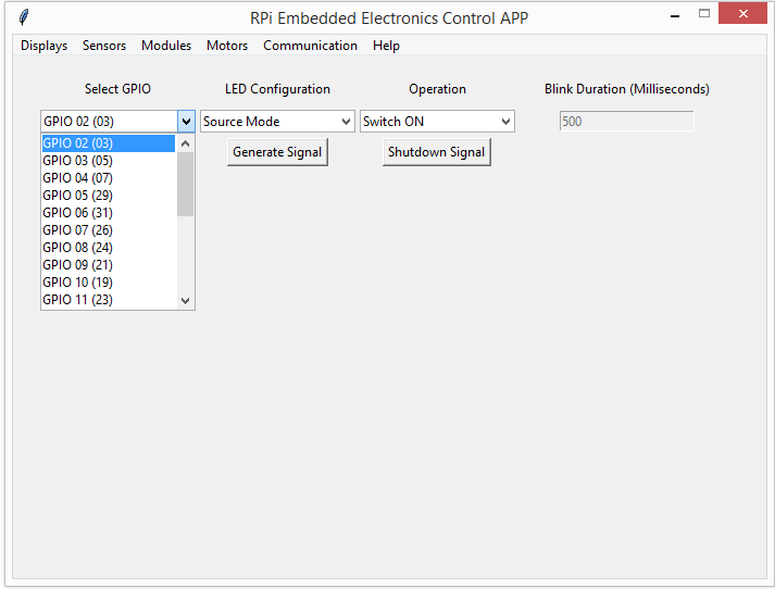
combo_LED_gpio = ttk.Combobox(LED_def, values=[“GPIO 02 (03)”, “GPIO 03 (05)”, “GPIO 04 (07)”, “GPIO 05 (29)”, “GPIO 06 (31)”, “GPIO 07 (26)”, “GPIO 08 (24)”,
“GPIO 09 (21)”, “GPIO 10 (19)”, “GPIO 11 (23)”, “GPIO 12 (32)”, “GPIO 13 (33)”, “GPIO 14 (08)”, “GPIO 15 (10)”
“GPIO 16 (36)”, “GPIO 17 (11)”, “GPIO 18 (12)”, “GPIO 19 (35)”, “GPIO 20 (38)”, “GPIO 21 (40)”, “GPIO 22 (15)”
“GPIO 23 (16)”, “GPIO 24 (18)”, “GPIO 25 (22)”, “GPIO 26 (37)”, “GPIO 27 (13)”,])
combo_LED_gpio.current(0)
combo_LED_gpio.grid(row = 2, column = 1)
label_LED_conf = Label(LED_def, text = “LED Configuration”)
label_LED_conf[“padx”]= 25
label_LED_conf[“pady”]= 10
label_LED_conf.grid(row = 1, column = 2)
combo_LED_config = ttk.Combobox(LED_def, values=[“Source Mode”, “Sink Mode”])
combo_LED_config.current(0)
combo_LED_config.grid(row = 2, column = 2)
label_LED_op = Label(LED_def, text = “Operation”)
label_LED_op[“padx”]= 25
label_LED_op[“pady”]= 10
label_LED_op.grid(row = 1, column = 3)
combo_LED_op = ttk.Combobox(LED_def, values=[“Switch ON”, “Switch OFF”, “Blink”])
combo_LED_op.current(0)
combo_LED_op.grid(row = 2, column = 3)
label_LED_duration = Label(LED_def, text = “Blink Duration (Milliseconds)”)
label_LED_duration[“padx”]= 25
label_LED_duration[“pady”]= 10
label_LED_duration.grid(row = 1, column = 4)
entry_LED_duration = Entry(LED_def)
entry_LED_duration.insert(0, “500”)
entry_LED_duration[‘state’] = DISABLED
entry_LED_duration.grid(row = 2, column = 4)
button_LED_signal = Button(LED_def, text = “Generate Signal”, command = thread_LED_signal)
button_LED_signal.grid(row = 3, column = 2, padx = 5, pady = 5)
button_LED_shutdown = Button(LED_def, text = “Shutdown Signal”, command = shutdown_LED_signal)
button_LED_shutdown.grid(row = 3, column = 3, padx = 5, pady = 5)
combo_LED_op.bind(‘<<ComboboxSelected>>’, active_blink)
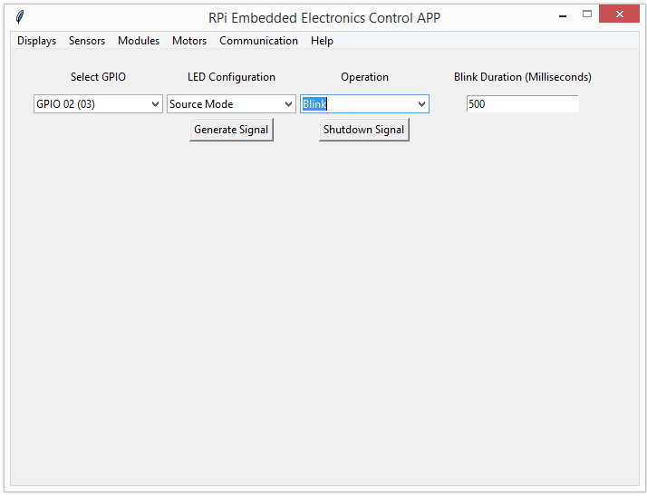
The GUI is loaded in a frame ‘LED_def’ below the menus. It contains a combobox to select the GPIO pin where the LED may be interfaced, a combobox to select whether the pin should act as current source or current sink to light up the LED, a combobox to select the desired LED operation (switch ON, switch OFF, or Blink) and an Entry to load value of blink interval in Milliseconds. There are label widgets on the top of each combobox and the entry widget to indicate their purpose. The entry is disabled by default and its state is changed to normal when ‘Blink’ operation is selected. This is done using <<ComboboxSelected>> virtual event of the Combobox widget. This event is bound to the combobox using bind() method of Tkinter/TTK and active_blink() function is executed on the occurrence of the event. In the active_blink() function, current index of the combobox is read and if it is 2 (corresponding to blink operation), the state of entry widget is set to normal.
def active_blink(event):
x = combo_LED_op.current()
if x == 2:
entry_LED_duration[‘state’] = NORMAL
Raspberry Pi’s embedded UI for the LED-driver circuit.
The GUI includes two buttons: one to start generating the signal that drives the LED and the other to stop it. The button (which generates the proper signal) must bind to the thread_LED_signal() function. The button (which stops the signal) must bind to the shutdown_LED_signal() function.
In the thread_LED_signal() function:
- The global variable is declared to reference that the thread is defined
- The generate_LED_signal() function is assigned as the target callable of the thread
The thread is started by the calling start() method of the threading module
def thread_LED_signal():
global thread_LED_driver
thread_LED_driver = MyThread(target = generate_LED_signal)
thread_LED_driver.start()
In the generate_LED_signal() function:
- The current values of the comboboxes are read using the widgets’ get() method
- The value of the selected GPIO pin is decoded to an integer number that corresponds to RPI’s Board Pin Numbers.
- The value entered by the user for the blink interval is validated to be an integer. Otherwise, 500 milliseconds is set as the default blink interval.
- The GPIO warning must be set to False and the board numbering system is selected for RPi. The selected GPIO pin is also set as an output.
Next, the conditions are matched for the selected LED operations with different cases for the LED driving method. Accordingly, the selected GPIO pin is set to logical HIGH or logical LOW to accomplish the operation under the chosen LED driving method.
To blink the LEDs, the state of the selected IO pin is toggled by a delay that’s entered by the user. To provide a delay, the sleep() method from the Time module is used. This method accepts delay in seconds.
def generate_LED_signal():
global gpio_pin
gpio_pin = combo_LED_gpio.get()
LED_config = combo_LED_config.get()
LED_op = combo_LED_op.get()
if gpio_pin == “GPIO 02 (03)”:
gpio_pin = 3
elif gpio_pin == “GPIO 03 (05)”:
gpio_pin = 5
elif gpio_pin == “GPIO 04 (07)”:
gpio_pin = 7
elif gpio_pin == “GPIO 14 (08)”:
gpio_pin = 8
elif gpio_pin == “GPIO 15 (10)”:
gpio_pin = 10
elif gpio_pin == “GPIO 18 (12)”:
gpio_pin = 12
elif gpio_pin == “GPIO 17 (11)”:
gpio_pin = 11
elif gpio_pin == “GPIO 27 (13)”:
gpio_pin = 13
elif gpio_pin == “GPIO 22 (15)”:
gpio_pin = 15
elif gpio_pin == “GPIO 23 (16)”:
gpio_pin = 16
elif gpio_pin == “GPIO 24 (18)”:
gpio_pin = 18
elif gpio_pin == “GPIO 10 (19)”:
gpio_pin = 19
elif gpio_pin == “GPIO 09 (21)”:
gpio_pin = 21
elif gpio_pin == “GPIO 11 (23)”:
gpio_pin = 23
elif gpio_pin == “GPIO 25 (22)”:
gpio_pin = 22
elif gpio_pin == “GPIO 08 (24)”:
gpio_pin = 24
elif gpio_pin == “GPIO 07 (26)”:
gpio_pin = 26
elif gpio_pin == “GPIO 05 (29)”:
gpio_pin = 29
elif gpio_pin == “GPIO 06 (31)”:
gpio_pin = 31
elif gpio_pin == “GPIO 12 (32)”:
gpio_pin = 32
elif gpio_pin == “GPIO 13 (33)”:
gpio_pin = 33
elif gpio_pin == “GPIO 19 (35)”:
gpio_pin = 35
elif gpio_pin == “GPIO 16 (36)”:
gpio_pin = 36
elif gpio_pin == “GPIO 26 (37)”:
gpio_pin = 37
elif gpio_pin == “GPIO 20 (38)”:
gpio_pin = 38
elif gpio_pin == “GPIO 21 (40)”:
gpio_pin = 40
else:
gpio_pin = 40
LED_duration = entry_LED_duration.get()
if LED_duration.isdigit():
LED_duration = int(LED_duration)
else:
LED_duration = 500
GPIO.setwarnings(False)
GPIO.setmode(GPIO.BOARD)
GPIO.setup(gpio_pin, GPIO.OUT)
if LED_op == “Switch ON”:
if LED_config == “Source Mode”:
GPIO.output(gpio_pin, GPIO.HIGH)
elif LED_config == “Sink Mode”:
GPIO.output(gpio_pin, GPIO.LOW)
elif LED_op == “Switch OFF”:
if LED_config == “Source Mode”:
GPIO.output(gpio_pin, GPIO.LOW)
elif LED_config == “Sink Mode”:
GPIO.output(gpio_pin, GPIO.HIGH)
elif LED_op == “Blink”:
GPIO.output(gpio_pin, GPIO.HIGH)
time.sleep(LED_duration/1000)
GPIO.output(gpio_pin, GPIO.LOW)
time.sleep(LED_duration/1000)
When pressing the shutdown signal button, the thread must be closed. So, in the shutdown_LED_signal() function, the global variable declared to reference the thread is defined. Then, the thread is closed using the stop() method of our modified threading class.
Finally, the cleanup of GPIO pins is done while terminating the signal.
def shutdown_LED_signal():
global thread_LED_driver
thread_LED_driver.stop()
GPIO.cleanup()
All the functions and GUI body statements are contained within the LED_driver() function. This single-function loads the GUI and implements an embedded LED driver.
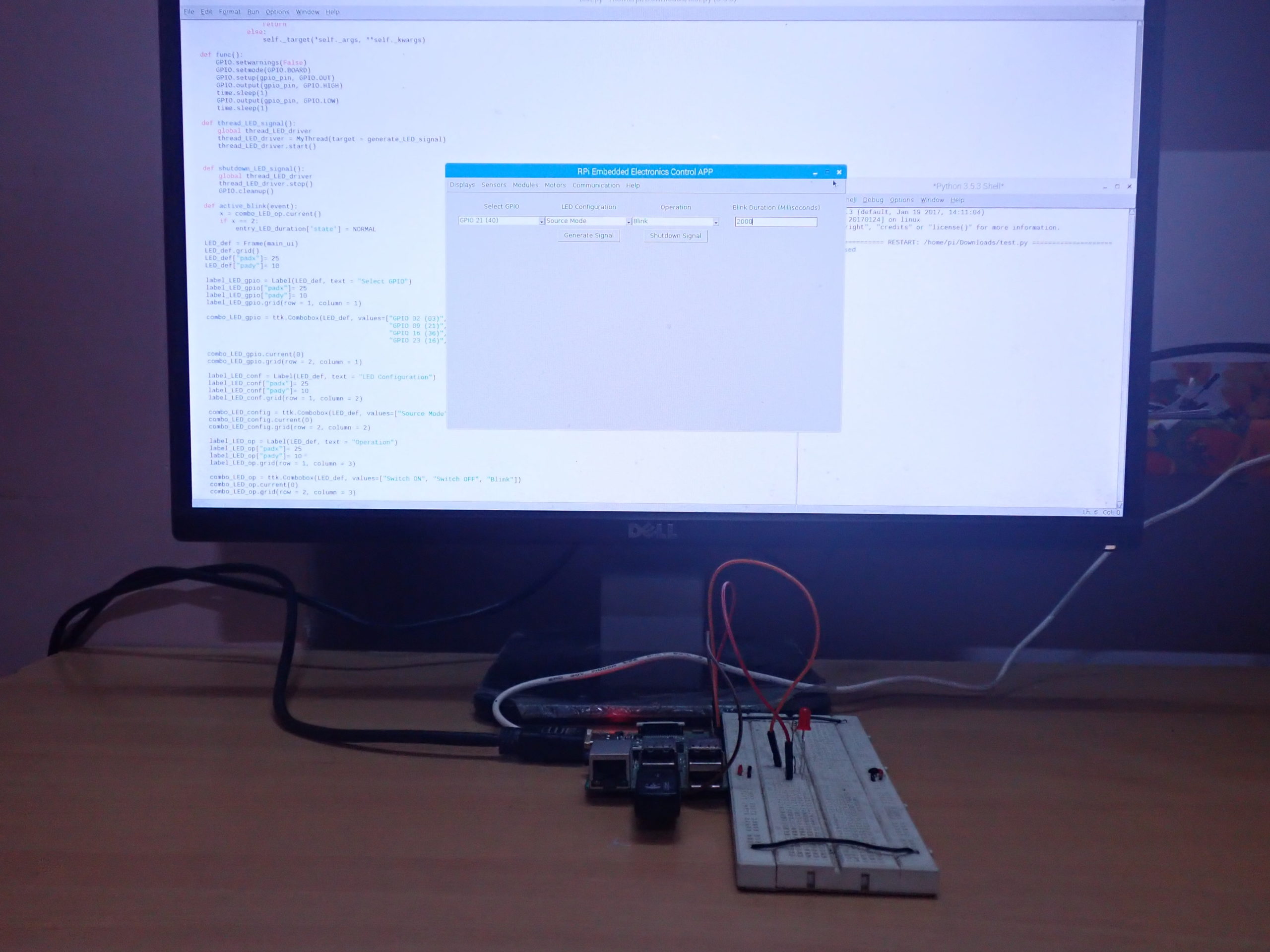
Working the project
The LED is prototyped on the breadboard so that it’s forward-biased when the current is sourced to it. The GUI app can control the LED regardless of how it’s interfaced with Raspberry Pi.
The GUI app takes direction from the user on how the LED is interfaced with RPi and the app is programmed to set the output of the IO pins accordingly to switch ON, OFF, or blink the LED.

Switching ON the LED from Raspberry Pi’s embedded UI.
It’s now possible to recognize the power of using a single-board computer compared to a microcontroller. With Raspberry Pi, we have controlled and driven LEDs in a manner that can be interfaced and driven from a GUI app.
Switching OFF the LEDs from Raspberry Pi’s embedded UI.
Such flexibility is generally not spared in a microcontroller-based application. A microcontroller would need interfacing buttons that engage with a digital input to implement such functionality. It would also require interfacing a numeric keypad to set the blink duration. A separate display device (SSD or LCD) would’ve been necessary to indicate the selected blink duration — and that involves a lot of hardware.
With Raspberry Pi, we simply have to use a single IO pin and implement the other functionalities from our GUI app.
Tkinter/TTK limitations
Tkinter/TTK allows for creating only static GUIs. If it would have supported a dynamic GUI, we could’ve added options to interface additional LEDs on the fly and controlled multiple LEDs at the same time using variable arrays.
Try-it-yourself
Tkinter/TTK does not support dynamic interfaces. But, we could’ve preloaded the GUI with options for all of RPi’s GPIO pins. Then, we could’ve populated these options using a GUI button by calling the grid() method for those options (when the user prompts to add the driver for a new LED).
In the next tutorial, we’ll learn how to use Raspberry Pi’s digital input and create a counter application by interfacing a button. Afterward, we’ll expand the same application to a numeric keypad for Raspberry Pi by employing a multiplexing technique.
Demonstration video:
Filed Under: Raspberry pi

Questions related to this article?
👉Ask and discuss on Electro-Tech-Online.com and EDAboard.com forums.
Tell Us What You Think!!
You must be logged in to post a comment.