The interrupts provided by the AVR microcontroller can be used for various purposes. Many applications can be made by using the ISR.

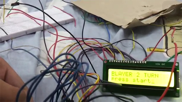
Fig. 1: Prototype of Arduino based Reaction Time Game
This feature of the AVR microcontroller will be used to make an LED following game which will test a user’s reaction time. There will be 4 LEDs and 4 corresponding buttons for each. After the game begins, a timer will start and a random LED will glow. The user will then have to press the button corresponding to that LED to turn it off. If the correct button is pressed, another LED will glow-up but if the wrong button is pressed, a penalty will be added and the same LED will continue to glow till the correct button is pressed. This will be repeated for a total of 5 turns. Player one will complete his turn and his time will be displayed and the second player will play.. At the end of the game, player with minimum time will be declared as the winner.
Pin Connections:
Port B and D of the Arduino are used to connect the LCD. Port B is used for connecting the EN and RS and Port D for connecting the 4 data bits.
LCD Pin Connections will be as follows:
(LCD Pin – Arduino Pin)
1) RS – PB2
2) EN – PB3
3) Vcc – 5v
4) Vee – Gnd
5) Vss – Gnd
6) DB4 – PD4
7) DB5 – PD5
8) DB6 – PD6
9) DB7 – PD7
Button Connections:
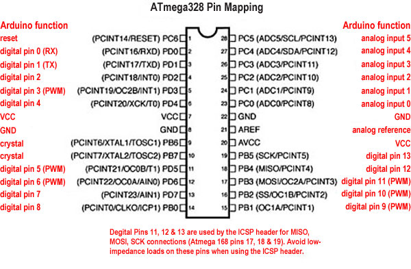
All the five external interrupts – PCINT0, PCINT1, PCINT2, INT0, INT1 will be used since there are 5 buttons and an independent interrupt needs to be generated for all the five buttons. The 5 buttons (push/switch) will then be connected to the following 5 pins of the Arduino as per following diagram.
> PD0 or PCINT16
> PB0 or PCINT0
> PD2 or INT0
> PD3 or INT1
> PC4 or PCINT12 (for start)

Fig. 2: Pin Diagram of Arduino Uno
Filed Under: Electronic Projects


Questions related to this article?
👉Ask and discuss on EDAboard.com and Electro-Tech-Online.com forums.
Tell Us What You Think!!
You must be logged in to post a comment.