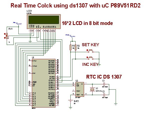
This project is to display ‘REAL TIME’ using microcontroller P89V51RD2 as well as RTC IC DS1307 such that it gives information related to Hours, Minutes, and Seconds. It also displays Date of the month, Month, Day of the week also with leap year compensation valid up to 2100.
Introduction to RTC
A Real Time Clock (RTC) is basically just like a watch – it runs on a battery and keeps time for you even when there is a power outage. Using an RTC, you can keep track of long timelines, even if you reprogram your microcontroller or a power plug.
The real time clock (RTC) is widely used device that provides accurate time and date for many applications. Many systems such as IBM pc come with RTC chip on mother board.RTC chip uses an internal battery which keeps time and date even when the power is off. In some microcontrollers have inbuilt RTC while others requires interfacing.
Most widely used RTC chip is DS1307 from Dallas Semiconductor. It uses external lithium battery of 3V to keep operating for over maximum 10 years in the absence of external power supply.DS1307 uses CMOS technology to keep power consumption low. According to datasheet of DS1307 from Dallas, it keeps track of “Seconds, Minutes, and Hours, Day of week, Date, Month and Year”
This chip provides facility of leap year compensation valid up to 2100. Leap year compensation is done by checking last two digits of year. All this information is provided in BCD or HEX formats.
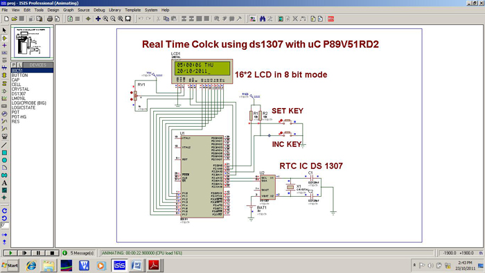
In our project we interface Dallas chip DS1307 with Philips microcontroller P89V51RD2. Microcontroller communicates with DS1307 by using I2C communication protocol. I2C interface can operate with data transfer rate up to 400k bits per second. Microcontroller can operate in transmitter or receiver mode at a time. Received data from RTC chip we displayed by using LCD. All the settings related to timing and date, we did it by using two push buttons.
Background
It is also possible to design Real Time Clock by using simply microcontroller or microprocessor but it will not be true Real Time Clock. It needs to adjust the days of various months as 30 or 31 (or sometime 29 or 28 in case of leap and non-leap year) in a year and in addition to that leap year compensation will tends to increase in the complexity of the program to great level or it may be such a difficult task to complete. It also seems difficult to get exact 1 second pulse or counting in microcontroller or microprocessor due to various external crystal frequencies availability and compatibility which drives the processor, it results in a deviation in time from real time or it affects the accuracy.
Problem Statement and Rough Idea
The project statement is to design a Real Time Clock with accuracy in time and date up to year 2100 with leap year compensation.
In our project we are interfaced microcontroller with Real Time Clock chip by I2C protocol along with LCD display for visualization. The block diagram shown below gives an idea about how we done this.
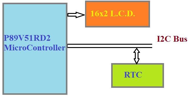
Fig 1: Block Diagram of Project
Working & Hardware Requirements
Working
In our project microcontroller communicate with the RTC chip on I2C protocol, in which microcontroller will work as a master and RTC chip as a slave. RTC chip is able to maintain the time of its own. Microcontroller will read the data from RTC chip which is initially written by uC , perform required operations on it and send that data to the LCD unit which will display it in human readable format. This process is going to continue for infinite time.
Hardware Requirement
Following components are required for designing the circuit of RTC
|
Sr. No. |
Part Description |
Qty. |
|
P89V51RD2 Board |
1 |
|
2 |
Real time clock IC DS1307 |
1 |
|
Crystal 32.768 kHz |
1 |
|
Capacitors 12.5 pF |
2 |
|
Coin Cell 3V |
1 |
|
Coin Cell Holder |
1 |
|
LCD 16 X 2 |
1 |
|
8 |
Potentiometer 10k |
1 |
|
9 |
General Purpose Circuit Board |
1 |
|
10 |
230:12 Transformer |
1 |
What is P89V51RD2 ?
It is an 80C51 microcontroller with 64 kB Flash and 1024 bytes of data RAM. A key feature of the P89V51RD2 is its X2 mode option. The design engineer can choose to run the application with the conventional 80C51 clock rate (12 clocks per machine cycle) or select the X2 mode (6 clocks per machine cycle) to achieve twice the throughput at the same clock frequency. Another way to benefit from this feature is to keep the same performance by reducing the clock frequency by half, thus dramatically reducing the EMI. The Flash program memory supports parallel programming, serial In-System Programming (ISP).
Parallel programming mode offers gang-programming at high speed, reducing programming costs and time to market. ISP allows a device to be reprogrammed in the end product under software control. The capability to field/update the application firmware makes a wide range of applications possible. The P89V51RD2 is also In-Application Programmable (IAP), allowing the Flash program memory to be reconfigured even while the application is running.
FEATURES OF P89V51RD2:
- 80C51 Central Processing Unit
- 5 V Operating voltage from 0 to 40 MHz
- 64 kB of on-chip Flash program memory with ISP (In-System Programming) and
- IAP (In-Application Programming)
- Supports 12-clock (default) or 6-clock mode selection via software or ISP
- SPI (Serial Peripheral Interface) and enhanced UART
- PCA (Programmable Counter Array) with PWM and Capture/Compare functions
- Four 8-bit I/O ports with three high-current Port 1 pins (16 mA each)
- Three 16-bit timers/counters
- Programmable Watchdog timer (WDT)
- Eight interrupt sources with four priority levels
- TTL- and CMOS-compatible logic level
- Pin diagram:
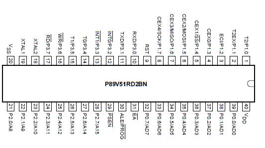
Fig 2: Pin Diagram of P89V51RD2
DETAILS OF DS1307
The DS1307 Serial Real Time Clock is a low power, full BCD clock/calendar plus 56 bytes of nonvolatile SRAM. Address and data are transferred serially via a 2-wire bi-directional bus. The clock/calendar provides seconds, minutes, hours, day, date, month, and year information. The end of the month date is automatically adjusted for months with less than 31 days, including corrections for leap year. The clock operates in either the 24-hour or 12-hour format with AM/PM indicator. The DS1307 has a built-in power sense circuit which detects power failures and automatically switches to the battery supply. Circuit for DS1307 has been shown in Circuit Diagram Tab2.
FEATURES OF DS1307
- Real time clock counts seconds, minutes, hours, date of the month, month, day of the Week, and year with leap year compensation valid up to 2100.
- 56 byte nonvolatile RAM for data storage
- 2-wire serial interface
- Programmable square wave output signal
- Automatic power-fail detect and switch circuitry
- Consumes less than 500 nA in battery backup mode with oscillator running
- Optional industrial temperature range 40°C to +85°C
- Available in 8-pin DIP or SOIC
- Recognized by Underwriters Laboratory
PIN DESCRIPTION
- VCC – Primary Power Supply
- X1, X2 – 32.768 kHz Crystal Connection
- VBAT – +3V Battery Input
- GND – Ground
- SDA – Serial Data
- SCL – Serial Clock
- SQW/OUT – Square wave/Output Driver
Pin diagram:

Fig 3: Pin Diagram of DS 1307
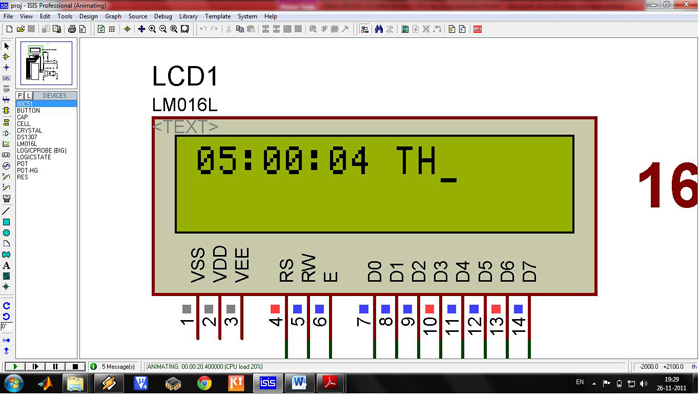
LCD
An LCD module has a display as well as display controller IC.
Software Requirements
Keil,Proteus and Flash Magic are major software requirements for this project.
I2C Communication
What is I2C?
Inter-IC-Communication
Originally, bus defined by Philips providing a simple way to talk between IC’s by using a minimum number of pins. A set of specifications to build a simple universal bus guaranteeing compatibility of parts (ICs) from different manufacturers: – Simple Hardware standards – Simple Software protocol standard. No specific wiring or connectors – most often it’s just PCB tracks .Has become a recognized standard throughout our industry.
Any device with the ability to initiate messages is called a ‘master’. It might know exactly what other chips are connected, in which case it simply addresses the one it wants, or there might be optional chips and it then checks what’s there by sending each address and seeing whether it gets any response (acknowledge).
An example might be a telephone with a micro in it. In some models, there could be EEPROM to guarantee memory data, in some models there might be an LCD display using an I2C driver. There can be software written to cover all possibilities. If the micro finds a display then it drives it, otherwise the program is arranged to skip that software code. I2C is the simplest of the buses in this presentation. Only two chips are involved in any one communication – the Master that initiates the signals and the one Slave that responded when addressed.
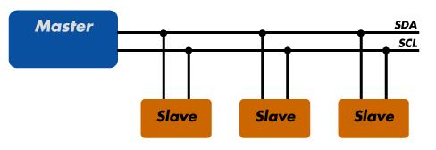
Fig 8: I2C
I2C Signals
- Bus not busy: Both data and clock lines remain HIGH.
- Start data transfer: A change in the state of the data line, from HIGH to LOW, while the clock is HIGH, defines a START condition.
- Stop data transfer: A change in the state of the data line, from LOW to HIGH, while the clock line is HIGH, defines the STOP condition.
- Data valid: The state of the data line represents valid data when, after a START condition, the data line is stable for the duration of the HIGH period of the clock signal. The data on the line must be changed during the LOW period of the clock signal. There is one clock pulse per bit of data
- Implementation
We implemented the project in following steps:
A. Coding and simulation – We wrote the program according to the need for communication with RTC chip. It is then edited, compiled and debugged into Keil uVision4 IDE. We designed required circuit in Proteus simulator. And .hex file generated by Keil IDE was transferred into uC in proteus. After many compilation and simulation we got good results.
B. Hardware requirement – We selected appropriate components with required specifications required for the designing of circuit.
C. Circuit Building and Testing – Then we mounted the components on general purpose PCB according to circuit design and then soldering is done. After soldering we take Bread Board Test (known as BBT) for short circuit. Then we corrected the errors in soldering. Then we downloaded program into uC chip by using FlashMagic downloader by NXP.
D. Enclosure Designing – We designed container or enclosure for whole circuit with appropriates outlets like LCD, ON-OFF switch, contrast control pot and power supply cord.
Connections
Following table shows the use of microcontroller pins in circuit designing
|
Micro-controller Pin |
Connection |
|
P1.0 – P1.7 |
D0- D7 of LCD |
|
P2.0 |
SET Button |
|
P2.1 |
RS pin of LCD |
|
P2.2 |
INC. Button |
|
P2.3 |
En pin of LCD |
|
P2.4 |
SCL of DS1307 |
|
P2.5 |
SCL of DS1307 |
Circuit Flowcharts & Proteus Outputs
FlowChart
a. Main program’s flowchart:

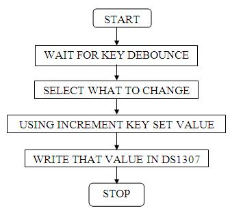
SET TIME FLOWCHART:
Proteus Window showing output
Circuit Images & Conclusion
Circuit Images
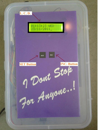
Image1: RTC Casing
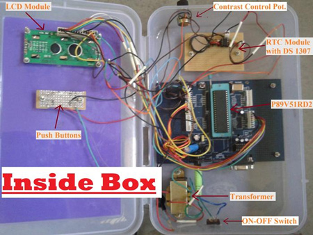
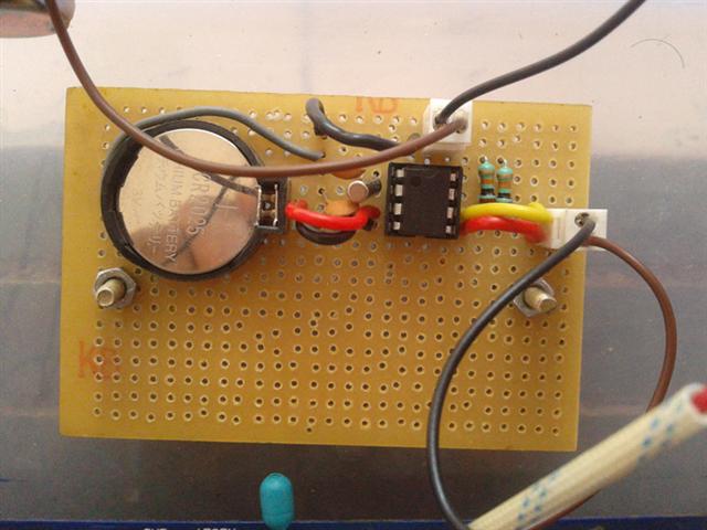
Image2: Inside RTC Casing
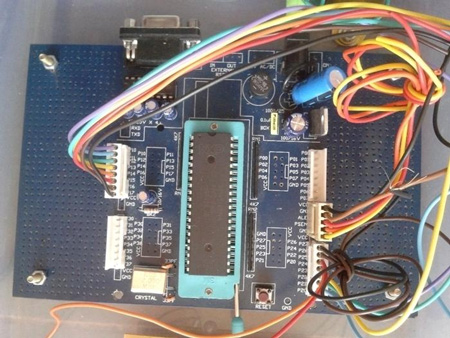
Image 3: Microntroller Board

Image4: LCD Output
Future scope:
- we can implement alarm
- It can be used to implement stopwatch
- Used in time sensitive applications
Conclusion:
We implemented RTC and displayed time, date on LCD by interfacing DS1307 chip with uC P89V51RD2. We studied application of I2C communication. We also studied use of softwares like Keil uVision and Proteus.
Project Source Code
###
//PROG. Version 11.10.23.17// interfacing ds1307 with 80C51#include<reg51.h>/* pins used for external h/w */sbit RS=P2^1; //connect p2.1 to rs pin of lcdsbit EN=P2^3; //connect p2.3 to en pin of lcdsbit SCL=P2^4; //i2c clock pinsbit SDA=P2^5; //i2c data pinsbit SET=P2^0; //set button pinsbit INR=P2^2; //increment button pin/* some required define(s)*/#define delay_us _nop_(); //generates 1 microsecond delay#define LCD P1 //port1 connected to LCD data pins#define SCLHIGH SCL=1;#define SCLLOW SCL=0;#define SDAHIGH SDA=1;#define SDALOW SDA=0;/*various functions used in whole program*/void _nop_(void);void init_lcd(void);void cmd_lcd(unsigned char);void write_lcd(unsigned char);void display_lcd(unsigned char *);void delay_ms(unsigned int);void init_rtc(void);void set_rtc(void);void strt_msg(void);void start(void);void stop(void);void send_byte(unsigned char);unsigned char receive_byte(unsigned char);void write_i2c(unsigned char,unsigned char,unsigned char);void set_value(void);void stpwtch(void);unsigned char read_i2c(unsigned char,unsigned char);//Give time here to set initial values to ds 1307 as specified in timekeeper registerunsigned char clock[]={0x00,0x59,0x23,0x04,0x20,0x10,0x11};//clock[]={seconds,minutes,hours,day_of_week,date,month,year};unsigned char stp[]={0x00,0x00,0x00};//stopwatch initial valueunsigned char *s[]={"SUN","MON","TUE","WED","THU","FRI","SAT"};unsigned char slave_ack,add=0,c,k,sas;unsigned int num;void main(void){init_lcd();strt_msg();//COMMENT THIS SECTION WHILE TRANSFRING PROGRAM SECOND TIME IN H/Winit_rtc();//always do thiswhile(1){if(SET==0)set_value();c=read_i2c(0xd0,0x02);//read hours register and display on LCD/* IMP rtc ds 1307 understands BCD no.sys. our 8051 uC understands HEX no.sys.and LCD requires ASCII data,,,,,,,,,,,,,,,,,,e.g. lets consider if data read from 1307 is 12 (BCD) i.e. 0001 0010 (BIN)so 8051 consider it as 18 (DECIMAL)x1=(18/16)+48=49(ASCII) i.e. lcd will show 1 andx2=(18%16)+48=50(ASCII) i.e. lcd will show 2i.e. 12 on lcd */write_lcd((c/16)+48);write_lcd((c%16)+48);write_lcd(':');sas = c & 0x20;c=read_i2c(0xd0,0x01);//read minutes register and display on LCDwrite_lcd((c/16)+48);write_lcd((c%16)+48);write_lcd(':');c=read_i2c(0xd0,0x00);//read seconds register and display on LCDwrite_lcd((c/16)+48);write_lcd((c%16)+48);write_lcd(' ');display_lcd(s[read_i2c(0xd0,0x03)]);//read day register and display//write_lcd(*s[read_i2c(0xd0,0x03)]);cmd_lcd(0xc0);// Go to starting position of 2nd line of LCDc=read_i2c(0xd0,0x04);//read date register and display on LCDwrite_lcd((c/16)+48);write_lcd((c%16)+48);write_lcd('/');c=read_i2c(0xd0,0x05);//read month register and display on LCDwrite_lcd((c/16)+48);write_lcd((c%16)+48);write_lcd('/');write_lcd('2'); //write 1st 2 digits of year bcoz only last 2 bits are stored in rtcwrite_lcd('0');c=read_i2c(0xd0,0x06);//read year register and display on LCDwrite_lcd((c/16)+48);write_lcd((c%16)+48);write_lcd(32); //THIS SECTION SHOWS am/pmif(sas == 0x20){display_lcd("AM");//write_lcd(49);}else{//write_lcd(48);display_lcd("PM");}delay_ms(110);cmd_lcd(0x01); // Go to starting position of 1st line of LCD}}void start(void) //starts i2c, if both SCK & SDA are idle{if(SCL==0) //check SCK. if SCK busy, return else SCK idlereturn;if(SDA==0) //check SDA. if SDA busy, return else SDA idlereturn;SDALOW //High to Low transition on data line SDA makes d start conditiondelay_usSCLLOW //clock lowdelay_us}void stop(void) //stops i2c, releasing the bus{SDALOW //data lowSCLHIGH //clock highdelay_usSDAHIGH //Low to High transition on data line SDA makes d stop conditiondelay_us}void send_byte(unsigned char c) //transmits one byte of data to i2c bus{unsigned mask=0x80;do //transmits 8 bits{if(c&mask) //set data line accordingly(0 or 1)SDAHIGH //data highelseSDALOW //data low//generate colckSCLHIGH //clock highdelay_usSCLLOW //clock lowdelay_usmask/=2; //shift mask}while(mask>0);SDAHIGH //release data line for acknowledgeSCLHIGH //send clock for acknowledgedelay_usslave_ack=SDA; //read data pin for acknowledgeSCLLOW //clock lowdelay_us}unsigned char receive_byte(unsigned char master_ack) //receives one byte of data from i2c bus{unsigned char c=0,mask=0x80;do //receive 8 bits{SCLHIGH //clock highdelay_usif(SDA==1) //read datac|=mask; //store dataSCLLOW //clock lowdelay_usmask/=2; //shift mask}while(mask>0);if(master_ack==1)SDAHIGH //don't acknowledgeelseSDALOW //acknowledgeSCLHIGH //clock highdelay_usSCLLOW //clock lowdelay_usSDAHIGH //data highreturn c;}void write_i2c(unsigned char device_id,unsigned char location,unsigned char c)//writes one byte of data(c) to slave device(device_id) at given address(location){do{start(); //starts i2c bussend_byte(device_id); //select slave deviceif(slave_ack==1) //if acknowledge not received, stop i2c busstop();}while(slave_ack==1); //loop until acknowledge is receivedsend_byte(location); //send address locationsend_byte(c); //send data to i2c busstop(); //stop i2c bus}unsigned char read_i2c(unsigned char device_id,unsigned char location)//reads one byte of data(c) from slave device(device_id) at given address(location){unsigned char c;do{start(); //starts i2c bussend_byte(device_id); //select slave deviceif(slave_ack==1) //if acknowledge not received, stop i2c busstop();}while(slave_ack==1); //loop until acknowledge is receivedsend_byte(location); //send address locationstop(); //stop i2c busstart(); //starts i2c bussend_byte(device_id+1); //select slave device in read modec=receive_byte(1); //receive data from i2c busstop(); //stop i2c busreturn c;}void init_lcd(void)//initialize lcd{delay_ms(10); //delay 10 millisecondscmd_lcd(0x0e); //lcd on, cursor ondelay_ms(10);cmd_lcd(0x38); //8 bit initialize, 5x7 character font, 16x2 displaydelay_ms(10);cmd_lcd(0x06); //right shift cursor automatically after each character is displayeddelay_ms(10);cmd_lcd(0x01); //clear lcddelay_ms(10);cmd_lcd (0x80);}void cmd_lcd(unsigned char c)//transmit command or instruction to lcd{EN=1;RS=0; //clear register select pinLCD=c; //load 8 bit dataEN=0; //clear enable pindelay_ms(2); //delay 2 milliseconds}void write_lcd(unsigned char c)//transmit a character to be displayed on lcd{EN=1; //set enable pinRS=1; //set register select pinLCD=c; //load 8 bit dataEN=0; //clear enable pindelay_ms(2); //delay 2 milliseconds}void display_lcd(unsigned char *s)//transmit a string to be displayed on lcd{while(*s)write_lcd(*s++);}void delay_ms(unsigned int i)//generates delay in milli seconds{unsigned int j;while(i-->0){for(j=0;j<500;j++){;}}}void set_value(void)//this function used for setting time using SET & INC buttons or pins{cmd_lcd(0x80);display_lcd("WELCOME TO TIME");cmd_lcd(0xC0);display_lcd(" SET WIZARD !!!");delay_ms(300);cmd_lcd(0x01);cmd_lcd(0x80);display_lcd(" SET YOUR RTC ?");cmd_lcd(0xC0);display_lcd("YES NEXT");while(1){if(SET==0){set_rtc();break;}if(INR==0){cmd_lcd(0x01);stpwtch();break;}}}void init_rtc(){while(add<=6) //update real time clock ic i.e. ds1307 with time{write_i2c(0xd0,add,clock[add]);add++;}}void strt_msg(){unsigned int i,j=0;display_lcd("Welcome to RTC");cmd_lcd(0xc0);display_lcd("<<<<<<<<>>>>>>>");delay_ms(300); //"...(#@#@#)..."cmd_lcd(0x01);display_lcd("SKIP INTRODUCTION");cmd_lcd(0xc0);display_lcd("YES NO");while(1){if(SET==0){delay_ms(40);break;}if(i==1000){j++;i=0;}if(INR==0|j==100){cmd_lcd(0x01);display_lcd("THIS PROJECT IS");cmd_lcd(0xc0);display_lcd("DONE BY T.E. ELN");delay_ms(500);cmd_lcd(0x01);display_lcd("<ROLL NO> <NAME>");delay_ms(250);cmd_lcd(0x01);display_lcd("38 AVINASH PATIL");cmd_lcd(0xc0);display_lcd("44 AMIT SALUNKHE");delay_ms(550);cmd_lcd(0x01);display_lcd("46 SWAPNIL SANKPAL");cmd_lcd(0xc0);display_lcd("48 SUMIT SHEKHAR");delay_ms(550);cmd_lcd(0x01);display_lcd("49 PRANAV SHINDE");delay_ms(300);cmd_lcd(0x01);display_lcd("STARTING RTC....");cmd_lcd(0xC0);for(i=0;i<17;i++){display_lcd(".");delay_ms(15);}break;}i++;}cmd_lcd(0x01);}void set_rtc(){unsigned char cnt=0x00;unsigned char q,p,i=0x00;while(1){if(SET==0x00){cnt++;delay_ms(50);cmd_lcd(0x01); // Go to starting position of 1st line of LCDcmd_lcd(0xc0);display_lcd("NEXT INC");cmd_lcd(0x80);switch(cnt){case 1:display_lcd("Minutes:");break;case 2:display_lcd("Hours :");break;case 3:display_lcd("Day :");break;case 4:display_lcd("Date :");break;case 5:display_lcd("Month :");break;case 6:display_lcd("Year :");}}if(INR==0)break;if(cnt>6)return;}cmd_lcd(0xc0);display_lcd("SAVE INC");while(1){ if(INR==0){delay_ms(10);cmd_lcd(0x8A); // Go to starting position of 2nd line of LCDp++;delay_ms(20);switch(cnt){case 1:if(p>59){p=0;}break;case 2:if(p>23){p=0;}break;case 3:if(p>7){p=0;}break;case 4:if(p>31){p=0;}break;case 5:if(p>12){p=0;}break;case 6:if(p>99){p=0;}}q=(p/10)<<4;q=q|(p%10);write_lcd((q/16)+48);write_lcd((q%16)+48);}if(SET==0)break;}write_i2c(0xD0,cnt,q);cmd_lcd(0x01);display_lcd("SAVING CHAGES");cmd_lcd(0xc0);display_lcd("PLEASE WAIT");// delay_ms(100);for(i=0;i<6;i++){display_lcd(".");delay_ms(40);}cmd_lcd(0x01);}###
Circuit Diagrams
Filed Under: Electronic Projects

Questions related to this article?
👉Ask and discuss on Electro-Tech-Online.com and EDAboard.com forums.
Tell Us What You Think!!
You must be logged in to post a comment.