A reed switch consists of two ferromagnetic nickel-iron wires and specially shaped contact blades (reeds) positioned in a hermetically sealed glass capsule with a gap between them and in a protective atmosphere. The glass capsule is filled with inert gas to prevent activation of the contacts. The ruthenium or rhodium plated contact surfaces are isolated from the outside environment, which protects the contacts from contamination.

Fig. 1: Diagrammatical Figures Showing Types of Reed Switch
Reed switches can be operated using a magnetic field generated by either a permanent magnet or current-carrying coil. They induce north (N) and south(S) poles on the reeds. The magnetic attractive force leads to closure of the reed contacts. Upon removal of the magnetic field, contact open again due to the elasticity of the reeds. There are Reed Switches which operate with permanent magnet, while there are Reed Switches operate with coils which can be magnetized by sending current through them.

Fig. 2: Permanent Magnet and Coil Based Reed Switches

Reed switches offer advantages of compact size, low weight, quick response time, long life and low cost. Common applications of reed switches are in reed relays, automotive sensors, security systems, robotics, toys and games.
In this article, we will be discussing about the basic electrical parameters of the Reed Switch. There are lots of technical terms associated with Reed Switch, which can be found in the datasheets.
SPECIFICATIONS-GENERAL
{C}{C}{C}{C}{C}{C}{C}{C}· Reed Switch Type
Type of reed switch specifies whether the reed switch is a dry reed switch or a mercury wetted reed switch.
Dry reed switch consists of ferromagnetic contact blades housed in a hermetically sealed glass container filled with an inert gas.
In mercury wetted reed switch, mercury is used as the contact material for electrical circuit; the reed contacts are covered with a film of mercury by capillary action. With each operation, the mercury film contact is renewed. Mercury wetted reed switches should be mounted in a specific orientation to avoid bridging the contacts due to mercury droplets.
Sensing Distance
Sensing Distance specifies the maximum distance between the magnet and the reed switch at which the reed switch functions satisfactorily.
Input Requirements
Input requirements specifies the magnitude of external magnetic field which to operate the reed switch.
Contact Position
Reed switches are available with gap in two positions: one at center and other off-center. In Center gap reed switches, gap or contacts are at the center of the reed switch. In Off Center gap reed switches, gap or contacts are not at the center of the reed switch.
Pole and Throw Specification
Pole and Throw specification refers to the switch contact configurations. The available options are
§ Single Pole Single Throw (SPST)
SPST switch has two terminals and it simply makes and breaks the contact between the two terminals
§ Single Pole Double Throw –SPDT
Also, known as changeover switch, it has three terminals labeled COM, A and B. COM can be connected to A in one state and to B in other.
§ Double Pole Single Throw(DPST)
DPST can be considered as two SPST switches with one actuator. A pair of ON-OFF Switch operates simultaneously.
§ Double Pole Double Throw(DPDT)
Similarly, two SPDT in parallel are operated by one actuator forms DPDT.
Based upon the Pole and Throw specifications, Reed switches are categorized as
·Form A ( also known as SPST-NO)
·Form B (also known as SPST-NC)
·Form C (also known as SPDT; changeover type)
·Form E (Bistable, latching type)
Configuration
Configuration specifies whether a switch is Normally Open or Normally Closed
Normally OPEN (NO) switches are those which remain in OFF state. On activation, the switch gets closed (or becomes ON). Exactly opposite Normally CLOSED (NC) switches are those which remain in ON state. On activating the switch, it gets opened (or becomes OFF).
Electrical Specifications
REED SWITCH SPECIFICATIONS –ELECTRICAL
· Pull-In (PI)
Consider a permanent magnet operated normally open Reed Switch. If we are bringing the magnet close to the Reed Switch, when it reaches a certain distance from the Reed Switch, the switch suddenly closes. This is called Pull-In and this distance is called Pull-In distance and is measured in mm or inches.
Fig. 3: Image Showing Pull-in Distance In A Reed Switch
Now let us consider a Coil operated normally open Reed Switch. If we are increasing the voltage across the coil, at certain voltage level, the switch closes suddenly. This voltage is called Pull-In voltage. It is measured in Volts (applied voltage across the coil at PI), Mille-amperes (current flowing through the coil at PI) or Ampere-Turns (product of current flowing at PI and the number of turns in the coil).
Fig. 4: Image Showing Pull-in Voltage In A Reed Switch
·Drop-Out (DO)
It is the distance from the magnet and the Reed Switch or the voltage applied across the coil, at which the previously closed switch opens again.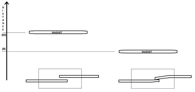
Fig. 5:Image Showing Drop Out Distance In A Reed Switch
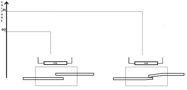
Fig. 6: Image Showing Drop Out Voltage In A Reed Switch
·Hysteresis
It can be observed that, the Pull-In happens at a particular distance or voltage. But once the PI has occurred, means the metals have made contact and if we slightly increase the distance or slightly reduce the voltage metals remain in contact, although it is not possible to make a contact at these points in normal cases.
Simply once the PI occurred, the DO will occur after a certain increase in distance or certain decrease in voltage only and vice versa. This effect is called Hysteresis.
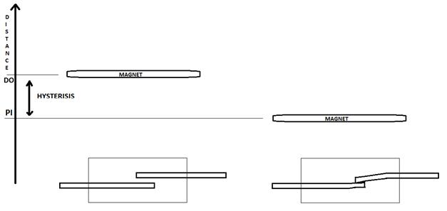
Fig. 7: Graphical Image Showing Distance Hysteresis In Reed Switches
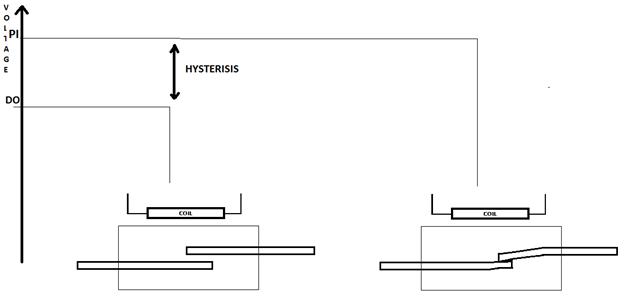
Fig. 8: Graphical Image Showing Voltage Hysteresis In A Typical Reed Switch
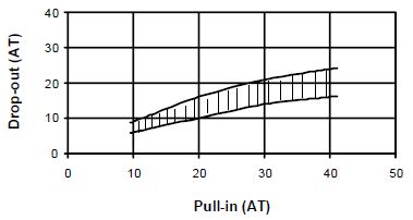
Fig. 9: Graph Showing Hysteresis In A Reed Switch
Hysteresis Graph
The above plot shows that that variation in hysteresis is for low ampere turns (AT) is very small and increases with higher AT. For a low hysteresis operation of the Reed Switch the magnetic influence on the switch should be kept low.
·Contact Resistance
Contact resistance is the resistance introduced by the contact metals of the Reed Switch in a circuit, in its closed (switch on) condition.

Fig. 10: Contact Resistance In A Reed Switch
This contact resistance is introduced by the resistance of metals, usually greater than resistance of copper.
There are basically two kind of contact resistance.
– Dynamic contact resistance
– Static contact resistance
Dynamic contact resistance
Dynamic contact resistance is the resistance experienced within the period of de-bouncing.
De-bouncing is an effect that exists in all kind of metallic switches which can make or break a contact. We normally expect that when we turn on a switch, it simply make contact instantly. But actually it is not like that. The switch continuously make and break contact for a few milliseconds, as if the metal pieces bouncing off from each other after hitting together, like a ball dropped on the floor does.
After the de-bouncing time only the switch makes permanent contact.

Fig. 11: Dynamic Contact Resistance In A Reed Switch
Since the contact is making and breaking continuously in a de-bouncing period, the resistance also increases and decreases accordingly; hence it is called dynamic resistance.
Before taking a decision about the state of the switch whether closed or open, one should wait until it finishes de-bouncing.
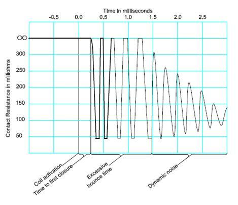
Fig. 12: Graphical Figure Showing Dynamic Contact Resistance Pattern
Dynamic contact resistance pattern
The above plot shows that the dynamic resistance falls significantly after the de- bounce period.
Electrical Specs (Contd)
{C}{C}{C}{C}{C}{C}{C}{C}· Static contact resistance
Static contact resistance is the resistance experienced after the period of de-bouncing i.e. in the stable period. In this region we will be having a constant low resistance for a DC voltage.
Insulation Resistance
Contact resistance is the resistance introduced by the contact metals of the Reed Switch in a circuit, in its open (switch off) condition. Ideally switches have infinite insulation resistance, but the Reed Switch usually has a finite very high Insulation resistance of the order of 1014 ohms.
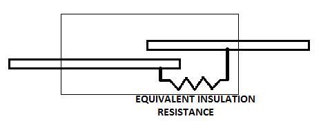
Fig. 13: Image Representing Insulation Resistance In A Reed Switch
Insulation resistance results in leakage current flow through the switch even when the switch is open. This can cause problems in high sensitive circuits. Hence one should select a switch with maximum insulation resistance.
·Stray Capacitance
In open state of the Reed Switch, there is only a very small gap between the two metal contacts. Hence it is possible to form a significant capacitance between this contact gap and we call it Stray Capacitance. Usually stray capacitance in the range of Pico Farads is found between the two metals.
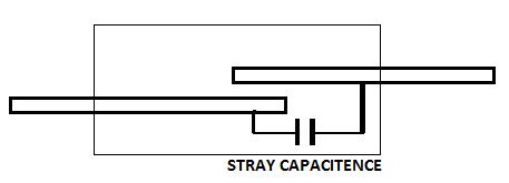
Fig. 14: Stray Capacitance In A Reed Switch
Stray capacitance introduces problems in high frequency circuits. At high frequency a capacitor appears to be short circuited. Hence the stray capacitance make the Reed Switch appears to be closed at high frequencies even if it is open. For high frequency designs one should select a Reed Switch with minimum stray capacitance.
·Contact Capacitance
A Reed switch in its closed state of the contact metals introduces not only resistance to the circuit, but a capacitance also, and we call such a capacitance as Contact Capacitance.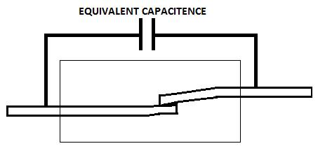
Fig. 15: Contact Capacitance In A Reed Switch
Reed Switches has contact capacitance of the range of 0.1 to 0.3 Pico farads. The contact capacitance also introduces certain problems in both high frequency and low frequency circuits. Hence one should select a Reed Switch with minimum contact capacitance.
{C}{C}{C}{C}{C}{C}{C}{C}·Common mode voltage
Common mode voltage is the maximum voltage that is allowed to apply on a Reed Switch while the Reed Switch is in open state (off state). At this condition the stray capacitance is charged up to this applied voltage. Whenever the switch closes all this voltage in the stray capacitance is discharged instantaneously. This can create an arc and can cause damage to the metals. Hence higher common mode voltages can reduce the life span of the Reed Switch.
For high voltage designs Reed Switches having higher common mode voltage is desired.
·Switching Voltage
It is the maximum voltage allowed to connect to a circuit using Reed Switch. A voltage higher than this value can cause an arc in the contact gap while the metals make contact and hence can damage the Reed Switch.
For high voltage and high operating frequency circuits Reed Switches with high switching voltage is desired.
·Switching Current
It is the maximum current that can be switched into a circuit without damaging the Reed Switch. Higher currents can considerably reduce the life of the Reed Switch by maintaining arc in the contact gap for significant amount of time while the metals make contact.
For high load connecting to the Reed Switch large switching current rating is desired for long lasting operations.
·Switching Wattage
It is the amount of power which is switched into a circuit by closing the Reed Switch. It is the product of voltage applied and the current flowing through the contacts.
For high power circuits one should select the Reed Switch having highest Switching wattage rating.
{C}{C}{C}{C}{C}{C}{C}{C}·Carry Current
It is the maximum current allowed to flow through the Reed Switch while the switch is already in closed state. In closed state, the Reed Switch can carry extremely high currents without damaging the metals.
·Breakdown Voltage
At voltages much higher than the switching voltages when applied to a Reed Switch can cause an arc even if the Reed Switch is in open state. It occurs due to dielectric break down at the contact gap due to high voltages. Voltage at which this break down occurs is called Break down voltage. Different Reed Switch has different dielectric material in the contact gap and hence its value varies in each type.
The Reed Switch should always be operated below the break down voltage. For high voltage circuits the designer should go for Reed Switch having highest break down voltage.
·Dielectric Absorption
The dielectric material in the contact gap can some time cause a delay in reflecting very small currents at the other end of the switch. This effect is due to the phenomenon of dielectric absorption. It is significant for currents lower than 1 Nano ampere
For high frequency applications the selected Reed Switch should have very minimum dielectric absorption rating.
·Contact Rating
Contact rating or power rating is defined as the product of maximum switching voltage and maximum switching current. Contact rating is also a very important of a reed switch (or any other switch). For reliable performance of the switch, contact rating should never be exceeded. Contact rating is also called contact capacitance or contact power allowance.
Contact rating is specified in units of W(Watts) or VA(Volt-Amperes).
Operational Specifications
SPECIFICATIONS –OPERATIONAL
Operate Time
It is the time consumes by the Reed Switch after closing for the first time till it finishes de-bouncing. In other words, it is the time required for the Reed Switch to enter the stable state after switched on.
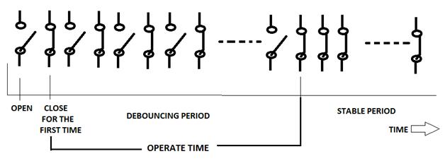
Fig. 16: Figure Showing Operate Time Specification in A Reed Switch
In high frequency circuit designs, especially in case of microcontroller based circuits the Reed Switch should have very small operate time.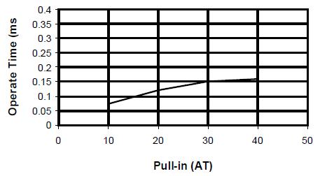
Fig. 17: Graphical Image Showing Operate Time Plot in Reed Switch
The above plot shows that with higher Pull-in AT the ReedSwitch gap increases taking a longer time for the contacts to close. Hence as the influence of the magnetic field increase the operating time decreases.
·Release Time
Suppose a Reed Switch is already closed due to a magnetic field. Even if we remove the magnetic field, the Reed Switch won’t open instantaneously. It remains closed for a very small time and after that period only it opens the contact. The time interval between the removing of magnetic field and the release of contact is called Release Time of a Reed Switch
For high frequency designs the Reed Switch should have minimum release time.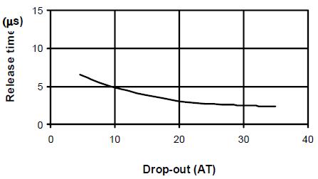
Fig. 18: Graph Showing Release Time Plot in A Reed Switch
The above plot shows that with increasing Drop-out AT the restoring forceincreases causing even faster release time. Hence as the influence of the magnetic field increase the releasing time also increases.
· Resonant Frequency
The metals used in the Reed Switch can bend and vibrate. Just like any other metal, these metals also have resonant frequency. Resonant frequency is that frequency of the metal in which if we made it to vibrate will generate maximum amplitude vibrations.
If we switch the Reed Switch at the resonant frequency of the metal plates, they vibrate with the maximum amplitude and hence there is a good chance for breaking the metals. Hence one should avoid operating Reed Switch at its resonant frequency.
·Maximum Operating Frequency
Maximum operating frequency indicates the maximum frequency at which reed switch can be operated or driven. In other words, This value specifies the maximum frequency at which switch can be opened or closed. This value is governed by the operate time and bounce time. If exceeded, it may lead to abnormal behavior. It is specified in Hz.
·Life Expectancy
Life expectancy specifies the number of cycles the switch can be switched ON and OFF. It is defined as the average number of cycles that a switch will achieve under specified load conditions before the contacts fail due to sticking, missing or excessive contact resistance. It is expressed as Mean Cycles Before failure (MCBF).
Mechanical Specifications
REED SWITCH SPECIFICATIONS –MECHANICAL
{C}{C}{C}{C}{C}{C}{C}{C}·Formation
Reed switches are available in various formations. They are as tabulated below
|
S. No |
Formation type |
Image |
|
1 |
Cropped |
|
|
2 |
SMD |
|
|
3 |
Welded |
|
|
4 |
Soldered |
|
|
5 |
Goal Post |
|
|
6 |
L Formed |
|
·Glass Encapsulated Length
This specification specifies the length of the glass capsule; the length of the leads and the terminals are not included in this specification
·Total Length
This specification specifies the total length of the reed switch, inclusive of the capsule length and the length of the leads.
· Diameter
This specification specifies the diameter of the glass capsule.
Certifications & Environmental Specs
SPECIFICATIONS –CERTIFICATIONS
{C}{C}{C}{C}{C}{C}{C}{C}· CE Certification
CE certification certifies that the product conform to the International commission rules for the approval of electrical equipment.
CSA Certification
Canadian Standards Association International certification signifies that the product has been evaluated by an authorized testing laboratory to determine that it meets applicable national standards (Canada or US).
UL Listed
Underwriters’ Laboratory provides certification on the product safety and their environmental claims
SPECIFICATIONS –ENVIRONMENTAL
{C}{C}{C}{C}{C}{C}{C}{C}· Hermetically Sealed
This specification specifies that the product is sealed airtight.
Weather Resistant/ Waterproof
This specification specifies that the product is sealed against moisture.
Operating Temperature
This specification specifies that the product can work satisfactorily in the specified temperature range.
Shock Resistance
This specification specifies that the product can sustain shock upto given ‘g’ levels & duration.
Vibrations
This specification specifies that the product can sustain vibrations upto given ‘g’ levels of specified frequencies.
REED SWITCH APPLICATIONS & ADVANTAGES
Reed Switches have the ability to switch up to 10,000 Volts, to switch currents up to 5 Amps to switch as low as 10 nanoVolts, to switch as low as 1 femptoAmp, to switch up to 7 GigaHertz. They have contact isolation up to 1015 W, they require no power or circuitry, and they offer latching features. They have the ability to operate over extreme temperature ranges and in all types of environments including air, water and vacuum.
Reed switches find applications in microphones, automobile crash sensors, defective lamp detection, vibration sensors, reed relays, fuel pumps, etc.
Filed Under: Articles


Questions related to this article?
👉Ask and discuss on EDAboard.com and Electro-Tech-Online.com forums.
Tell Us What You Think!!
You must be logged in to post a comment.