The remote control based motor circuit described below is used to on and off the motor just by clicking your TV or AC remote. This low cost circuit is based on IR sensor, transistor with few more components to “on” the relay and a motor is connected with the relay which also become “on”. After receiving the second pulse motor become “off”. You can control your motor from 5-7 meters range.It can be operated with all most all the remotes present in home as it works on 38Khz frequency. You do not require to move from your place, just press the remote device become “on” and “off” respectively by getting signals from remote. The circuit also provides you the visual indication (“on” or “off”) of the device with the help of LED.
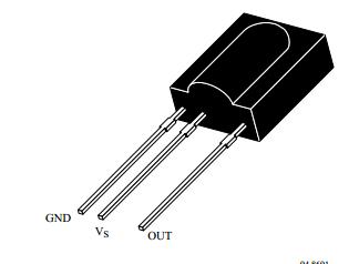
This is a simple circuit based on infrared sensor IC TSOP1738. TSOP1738 contains photo detector and preamplifier both in one package. It is a three terminal device. Pin 1 is for ground, Pin 2 is for power supply and pin 3 is used as output. Pin diagram of TSOP1738 is shown below. Take care while connecting the pins of TSOP1738. Wrong lead connection of TSOP1738 may lead to sensor damage.
This circuit is build around IR receiver module TSOP1738 and two transistors with few more discrete components. Initially when power supply is applied, pin 3 (out pin) of IC1 is high. This is fed to the transistor T1 via a diode D1 which makes collector of transistor T1 high. This means when no button from remote is pressed transistor T1 is non-conducting while Transistor T2 is in cut off mode hence relay will not energize.
Whenever you press any button of remote, IR beam fall on the TSOP1738 sensor which makes its output pin 3 low and transistor T1 start conducting and transistor T2 also starts conducting which in turn switch on the relay connected at the output. The LED connected at the output glow only when device is on otherwise it remains off.
We have connected a resistor at pin 2 of IC1 because excess voltage may destroy the sensor TSOP1738. Take care while purchasing the TSOP1738 because others sensors work on different frequency and in that case frequency of remote will not match with the sensor and your device will not work.
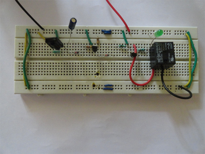
Circuit Diagrams
Project Video
Filed Under: Electronic Projects
Filed Under: Electronic Projects

Questions related to this article?
👉Ask and discuss on EDAboard.com and Electro-Tech-Online.com forums.
Tell Us What You Think!!
You must be logged in to post a comment.