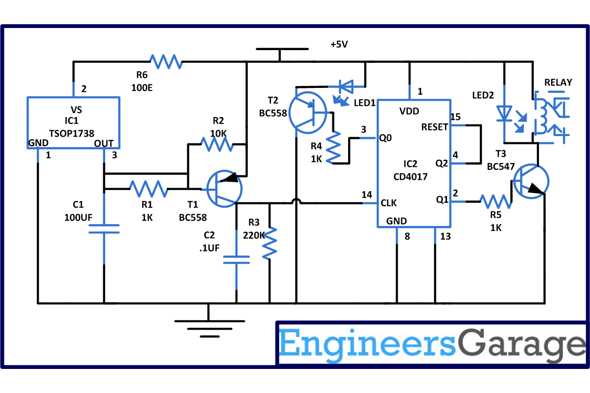
Remote control toy car circuit can be used to on and off the motor of the toy car with the help of your remote. You can use any remote of TV, AC, DVD player to control the movement of motors. This low cost circuit is based on the CD4017 counter IC which receives trigger pulse from IR sensor and switch ON the relay. With the relay, motors are connected which also get switched ON. Upon receiving the second pulse motor gets turned OFF. You can control your toy car upto 5 meters range.
[[wysiwyg_imageupload:8575:]]
Fig. 1: Prototype Of Remote Controlled Toy Car Circuit On Breadboard
This remote controlled toy car circuit is based on infrared sensor IC TSOP1738. TSOP1738 contains photo detector and preamplifier in one package. It is three terminal device having pin 1 configured for ground, pin 2 for power supply and pin 3 as output. Pin diagram of TSOP1738 is shown below. Take care while connecting the pins of TSOP1738. Wrong lead connection of TSOP1738 may lead to sensor damage.
Assemble the circuit as shown in circuit diagram and apply power supply. When you press the remote, 38KHz infrared rays (IR)are generated through remote control (which used as transmitter) and these rays are received by TSOP1738 which act as receiver in our circuit. TSOP 1738 is interfaced with the transistor T1 that amplifies its signals.
Now these amplified signals are fed into the clock input pin 14 of IC2. Therefore, when you press any button on of the remote clock input goes high and the motor connected to pin 3 and pin 2 starts rotating with the help of relay.
Note: You can also directly connect the motor without relay but take care of specifications of motor you are connecting.
Circuit Diagrams
Project Components
Project Video
Filed Under: Electronic Projects
Filed Under: Electronic Projects


Questions related to this article?
👉Ask and discuss on EDAboard.com and Electro-Tech-Online.com forums.
Tell Us What You Think!!
You must be logged in to post a comment.