The project has used 434 MHz RF Module which is capable of transmitting 4-bit data to a receiver. Thus by pairing a single receiver to the transmitter, at most four devices can be remotely controlled if they are directly interfaced to the receiver module without any other logical circuit in between. If some logical circuit or microcontroller based circuit is used at the receiver end, with a single receiver module maximum 16 devices (as 16 different signals can be sent in a 4-bit data) can be controlled.

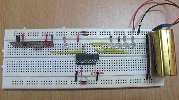
Fig. 1: Prototype of RF Remote Control
In the project LEDs are shown as loads. These LEDs are switched on/off using the RF transmission. The LEDs can be replaced by any other load or appliance connected through a relay to the receiver circuit. The basic setup of 434 MHz RF module has been used in the project. Learn about fundamentals of RF transmission and the basic model of RF transmitter and receiver.
Components Required
| COMPONENTS REQUIRED | NO. |
|---|---|
| RF Transmitter and receiver module (434 MHz) | 1 |
| HT12E/HT12D Encoder IC | 1 |
| LED | 1 |
| Resister-10KΩ (Quarter watt) | 8 |
| Resister-1MΩ (Quarter watt) | 1 |
| Battery – 9V | 2 |
| Breadboard | 2 |
| Push-to-on Switches | 4 |
| Connecting wires |

Fig. 2: Block Diagram of RF Remote Control
Circuit Connections
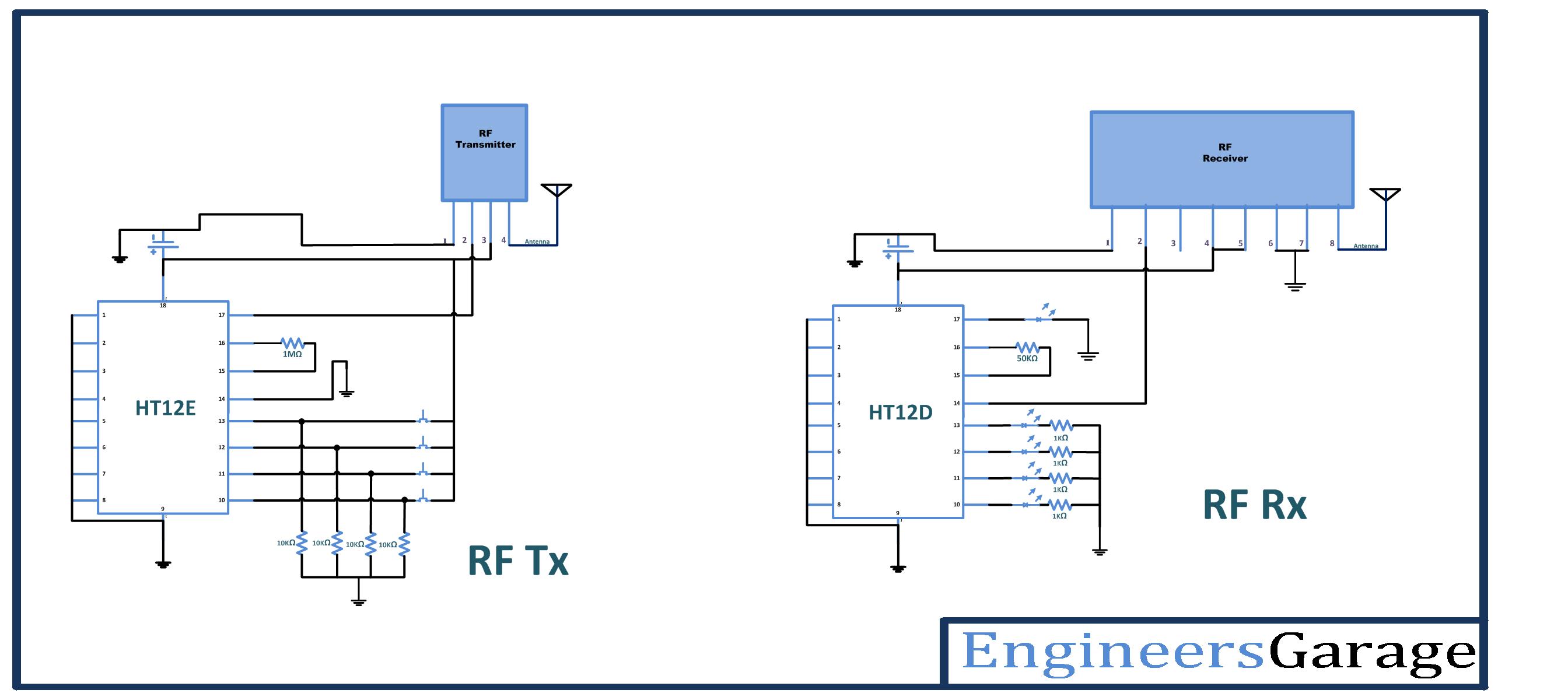
The circuit connections of RF module are same as done in setting up the basic model of RF Transmitter and Receiver. In addition to the setup of RF module, four switches have been connected at the data pins 10 to 13 designated as D0 to D3 of the encoder IC HT12E. These Push-to-on switches are connected through 10K ohm pull-up resistors. The address pins 1 to 8 of the encoder IC are hard wired to ground to assign the transmitter an address of 0x00. The pin 14 of the encoder IC which is active low is also hard-wired to ground to enable uninterrupted transmission of control signal to the RF receiver.
At the receiver module, the loads are connected at the data pins 10 to 13 designated as D0 to D3 of the decoder IC HT12D. In the project, LEDs are used as loads and they are directly interfaced to the decoder IC. Therefore, maximum 4 LEDs/other loads can be remote controlled using this project. The LEDs are connected in series with 1K ohm pull-up resistors to the ground. Therefore, on receiving a HIGH signal corresponding to a HIGH bit at that data pin, the respective LED starts glowing. On receiving a LOW signal corresponding to a LOW bit at that data pin, the respective LED stops glowing. In the same respect if any other load would have been connected to the data pins, it would have switched on or off depending upon its circuit configuration on receiving HIGH or LOW bit at the data pins. The address pins 1 to 8 of the decoder IC HT12D are hard wired to ground in order to match the 0x00 address of the RF transmitter.

Fig. 3: Prototype of RF Remote Receiver
Since, the transmitter has been configured for uninterrupted transmission, any change in the status of switches at the transmitter end immediately reflect a change in on/off status of the LEDs or loads at the receiver end. Due to latch-type nature of data pins of the decoder IC HT12D, any change in the on/off status of LEDs or loads remain persistent until a new signal with reverse bit status is received from the transmitter module. Hence, pressing on or off the switches at the transmitter module instantly switches on or off the LEDs respectively.
How the Circuit Works
The RF module transmits the 4-bit data as it is expected to do. By default, the data pins of the encoder HT12E receive a LOW signal as they are grounded via 10K ohm resistors. Therefore, by default LOW bits are transmitted and same LOW bits are received at the data pins of decoder IC HT12D and the LEDs remain off. The push-to-on switches are connected to the data pins with other terminal of each switch connected to the power supply. When a switch is pressed, the respective pin starts receiving a HIGH signal.
Since the pin 14 of encoder IC is hard-wired to ground and transmitter generates an uninterrupted transmission of data, as a HIGH signal is detected at a data pin of the encoder IC, a HIGH signal corresponding to that data bit is immediately transmitted and a HIGH bit is decoded at the respective data pin of the decoder IC HT12D. When a HIGH signal is received at a data pin of the decoder IC, current starts flowing through the LED which is connected to the pin with a pull-up resistor of 1K ohm in series to the ground. Thus the LED starts glowing on receiving a HIGH bit at the respective data pin of the decoder IC.
If the respective switch at encoder IC is pressed off, the corresponding data bit at the encoder is again set to LOW and a LOW bit is received at the respective data bit of the decoder IC. Thereof, the LED connected to the respective data pin of the decoder IC is again switched to off.
The experiment has used LEDs as loads; however any load can be connected to the data pins of the decoder IC. A load operating on AC current can also be interfaced to the receiver module using a relay connected to the data pin of the decoder IC through a transistor circuit. A maximum of four devices can be controlled on or off with this project.
You may also like:
Circuit Diagrams
Filed Under: Tutorials


Questions related to this article?
👉Ask and discuss on Electro-Tech-Online.com and EDAboard.com forums.
Tell Us What You Think!!
You must be logged in to post a comment.