The temperature controller or monitoring system is one of the most required systems in almost all processing and manufacturing industries. Here, the given application demonstrates completely new kind of temperature monitoring and control system. It monitors temperature, display it, send signal wirelessly to remote monitoring node and give alarm signal to this remote node when temperature exceeds beyond critical limit. It performs following tasks
· It continuously senses current temperature using temperature sensor
· Display current temperature on LCD
· Transmit signal to remote monitoring node if temperature is continuously increasing or decreasing
· Transmit signal to trigger alarm on remote monitoring node when temperature exceeds critical limit
· Remote monitoring node continuously indicates temperature is decreasing / increasing with help of GREEN / RED led
· It actuates alarm through relay when it receives alarm trigger signal from transmitter

Fig. 1: Prototype of AVR ATMega32 based Temperature Monitoring System
The advantage of this system is one can remotely monitor system temperature and get the idea of whether temperature is constant / increasing / decreasing. Another and most important advantage is when temperature exceeds specified limit the alarm signal is available on remote terminal. This can help in taking any immediate or automatic action.
System block diagram
As shown in figure, there are two nodes one is sensor-monitor-transmitter node and another is remote receiver node.
Sensor monitor transmitter node
It is made up of temperature sensor, micro-controller, LCD panel, RF encoder and RF ASK transmitter.
Temperature sensor : it senses temperature. It’s a transducer. It gives change in output voltage as temperature changes.
Micro-controller : it performs following tasks
· It takes analog voltage input from sensor. Converts it into digital equivalent using built in ADC. Then convert it into decimal to display it
· It display this temperature value on LCD to monitor temperature locally
· It sends signal to remote monitoring node if temperature is not steady – means either its increasing or decreasing. If temperature is constant it does not transmit
· When temperature exceeds specified limit it transmits signal to trigger alarm on remote monitoring node

Fig. 2: Block Diagram of AVR ATMega32 based Temperature Monitoring System
RF encoder : it encodes 4-bit parallel data given by micro-controller into serial bit stream.
RF ASK transmitter : it transmits serial bit stream given by RF encoder over 434 MHz carrier. It uses ASK modulation.
Remote monitoring node
It includes RF ASK receiver, RF decoder, LEDs and relay
RF ASK receiver : it receives bit stream transmitted by RF ASK transmitter by demodulating it and gives it to RF decoder
RF decoder : it decodes serial bit stream and gives parallel 4 bit data output
LEDs : RED led indicates temperature is increasing and GREEN led indicates temperature is decreasing
Relay : it is used as actuator. It can actuate any kind of alarm like audio signal (horn, bell or buzzer) visual signal (blinking lamp) etc.
Working & Operations
Sensor monitor transmitter node circuit
As shown in figure circuit is made up of temperature sensor LM35, AVR micro-controller ATMega32, RF encoder HT12E, 16×2 LCD and RF transmitter.
· Output of LM35 is connected to ADC input of ATMega32
· Data pins D0 – D7 of LCD are connected to PORTC
· Two control pins RS(4) and En(6) of LCD are connected to PORTD pins PD0 and PD1 respectively. RW(5) pin is grounded
· Data input pins D0 – D3 of HT12E are connected to PORTB pins PB0 – PB3. Transmit Enable (TE) pin is connected to PB4. One BLUE LED is also connected to this pin to indicate transmission
· Serial output of HT12E is connected to data input Din of RF Tx
· 16MHz crystal and two 22 pf capacitors are connected with crystal input pins as shown
Remote monitor node circuit
It is made up of RF decoder HT12D, RF receiver, few LEDs and transistors and one C/O (change over) type relay
· Data output Dout of RF receiver is connected to serial input of HT12D
· Data output D0 of HT12D drives relay RL1 through two transistors Q1 and Q2 connected in Darlington configuration
· Data output D1 drives RED LED, D2 drives GREEN LED and D3 drives BLUE LED as shown
· Valid Transmission (VT) pin drives one RED LED through NPN transistor Q3 to indicate receiver is active
Circuit operation
· Micro-controller reads temperature sensed by temperature sensor and display it on LCD
· Everytime it checks whether new temperature value is same as previous temperature value. If last read temperature value is within ± 2o cel. Then it will not transmit signal to remote monitoring node every time. It will only transmit signal once to indicate temperature is steady on BLUE LED
· If the new temperature value read is more than previous temperature value then 4 bit data (D0 – D3) is transmitted such a way that on remote monitoring node RED LED will glow
· Similarly if new temperature value read is less than previous temperature value then 4 bit data is transmitted such a way that on remote monitoring node GREEN LED will glow
· If temperature exceeds 150o then 4 bit data is sent that will switch on the relay to give alarm signal. Afterwards when temperature decreases to 140o data is transmitted to switch off relay
· On transmitter side BLUE LED blinks when data is transmitted and RED LED on receiver side blinks to indicate data is received
Software
The software program embedded into AVR micro controller is responsible for complete circuit operation. It performs following tasks
1. Initializes LCD and built in ADC
2. Reads analog voltage values of sensor and converts it in to digital equivalent using built in ADC
3. It converts this digital value into equivalent decimal value and display it on LCD
4. Compare recent value with previous value to make decision for data transmission
5. Transmit proper data to remote monitor node to indicate temperature is increasing or decreasing
6. Transmit data to activate alarm when temperature exceeds beyond limit
The program is written in C language. It is compiled using AVR GCC compiler and simulated using AVR simulator for ATMega32 micro-controller. Both AVR GCC compiler and AVR simulator are available builtin in AVR studio (V4) software tool. When program is compiled successfully it generates HEX file. This file can be loaded into target device ATMege32 using any suitable programmer (like ponyprog). Here is the complete program code with necessary comments.
Project Source Code
###


#include <avr/io.h>
#include <util/delay.h>
#include <string.h>
unsigned int value,pre_val,upper_limit,lower_limit,upper_limit_flag=0, out_of_range_flag=0;
void senddata(unsigned char data)         // function to send data to LCD
 {
      _delay_ms(1);
      PORTD=(1<<PD0);
      PORTC=data;
      PORTD=(1<<PD0)|(1<<PD1);
      PORTD=(1<<PD0)|(0<<PD1);
 }
void sendcmd(unsigned char cmd)     // function to send command to LCD
 {
      //PORTD = PORTD & 0xFB;
      _delay_ms(1);
      PORTD=(0<<PD0);
      PORTC=cmd;
      PORTD=(1<<PD1);
      PORTD=(0<<PD1);
 }
void printstr(unsigned char *s)     // function to display string on LCD
{
      uint8_t l,i;
      l = strlen(s);                      // get the length of string
      for(i=0;i<l;i++)
      {
            senddata(*s);                 // write every char one by one
            s++;
      }
}
void transmit(unsigned int val)           // transmit function
  {
      if(val<lower_limit)                 // if new temperature value is
        {                                 // less
             PORTB |= 0x0C;              // transmit data to make RED LED
             PORTB &= 0xED;              // off and GREEN LED ON
             _delay_ms(100);
              PORTB |= 0x10;
              out_of_range_flag=1;        // set out of range flag
        }
      else if(val>upper_limit)            // if new temperature value is
        {                                 // more
              PORTB |= 0x0A;              // transmit data to make RED LED
              PORTB &= 0xEB;              // ON and GREEN LED OFF
             _delay_ms(100);
             PORTB |= 0x10;
             out_of_range_flag=1;
        }
      if((val>=lower_limit) && (value<=upper_limit)) // if new value is
        {                                             // within range
            if(out_of_range_flag==1)      // only one time
              {
                  PORTB |= 0x06;          // transmit data to ON BLUE
                  PORTB &= 0xE7;          // LED and off other two LEDs
                  _delay_ms(100);
                  PORTB |= 0x10;
                  out_of_range_flag=0;
              }
        }
       if(val>=150)                 // if temperature value exceeds limit
       {
           if(upper_limit_flag==0) // only one time
              {
                  PORTB |= 0x01;    // transmit data to switch ON
                  PORTB &= 0xEF;    // RELAY
                  _delay_ms(100);
                  PORTB |= 0x10;
                  upper_limit_flag=1;
              }
        }
      else if(val<=140)             // if temperature decreases
        {
           if(upper_limit_flag==1) // only one time
              {
                  PORTB &= 0xEE;    // transmit data to switch off
                 _delay_ms(100);   // RELAY
                  PORTB |= 0x10;
                  upper_limit_flag=0;
              }
        }
  }
unsigned int convert_n_display()    // convert 10 bit ADC value into
  {                                 // decimal and ASCII
      unsigned int tmp1,tmp2,tmp3,t,t1,a,temp_value;
      unsigned char asci[3];
      tmp1 = (ADCL & 0x0F);
      tmp2 = ADCL >> 4;
      tmp3 = (ADCH & 0x0F);
      tmp2 = tmp2*16;
      tmp3 = tmp3*256;
      t = tmp1+tmp2+tmp3;
      temp_value = t;
      if(t>=100)
        {
            a=2;
            while(t>=10)
            {
                  t1=t%10;
                  asci[a]=t1+0x30;
                  t=t/10;
                  a--;
              }
            asci[0]=t+0x30;
        }
      else
        {
            t1=t%10;
            asci[2]=t1+0x30;
            t=t/10;
            asci[1]=t+0x30;
            asci[0]=0x30;
        }
      sendcmd(0x80);
      printstr("temperature:");
     sendcmd(0xC0);
     senddata(asci[0]);
      senddata(asci[1]);
      senddata(asci[2]);
      printstr(" deg Cel");
      return temp_value;            // return decimal value
  }
void adc_init()                     // initialize built in ADC
  {
      ADMUX = (1<<REFS0);
      ADCSRA =(1<<ADPS2) | (1<<ADPS1) | (0<<ADPS0);
      ADMUX=0x00;
  }
void lcd_init()                     // initialize LCD and
  {
       sendcmd(0x3E);
      sendcmd(0x0E);
       sendcmd(0x01);
       sendcmd(0x82);
       printstr("temperature");     // display message
       sendcmd(0xC5);
       printstr("sensor");
  }
void main()
 {
      DDRD=0x07;                    // port D 3 bits as output
      PORTD=0x00;
      DDRC=0xFF;                    // port C as output
      PORTC=0x00;
      DDRB = 0x1F;                  // port B as output
      PORTB = 0x10;
      lcd_init();
      _delay_ms(2000);              // wait for 2 sec
      adc_init();
      while(1)
        {
         ADCSRA = (1<<ADEN) | (1<<ADSC);     // start and enable ADC
         while(!(ADCSRA & (1<<ADIF)));       // wait till conversion end
         ADCSRA = (1<<ADIF);
         value = convert_n_display();        // get temperature value
         transmit(value);                    // transmit to remote node
         pre_val = value;                    // save value
         upper_limit = pre_val+2;            // set upper and
         lower_limit = pre_val-2;            // lower limit
         _delay_ms(2000);                    // wait for 2 sec
        }
  }

###
Circuit Diagrams
| Circuit-Diagram-AVR-ATMega32-Based-Temperature-Monitoring-System | 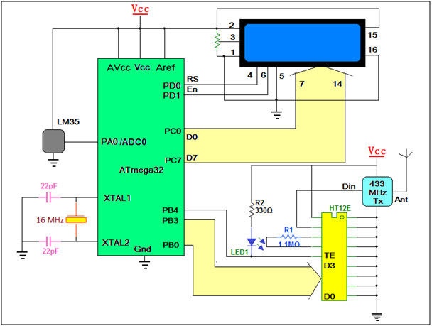 |
| Circuit-Diagram-Remote-Monitoring-Node-AVR-ATMega32-Based-Temperature-Monitoring-System | 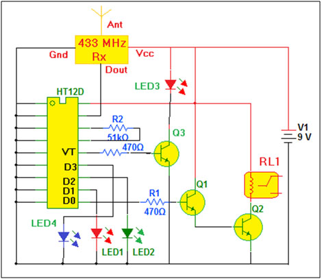 |
Project Video
Filed Under: Electronic Projects
Filed Under: Electronic Projects

Questions related to this article?
👉Ask and discuss on Electro-Tech-Online.com and EDAboard.com forums.
Tell Us What You Think!!
You must be logged in to post a comment.