Resistance is a passive component commonly used to restrict electric current. This article explains the resistor color code and how to measure resistance value. Every resistance follows a color coding scheme and its values is determined by decoding the colors which are marked on it. If you will look at any resistance you will find some colored strips on it, which is used to identify its value.
A resistance will have three to six colored bands on it. A set of ten colors are used to represent the value of resistance. Every color represents a numeric digit from 0-9. Two additional colors are generally used to represent the multiplier of the tolerance values.
Resistor Color Code for six (6) color band resistor
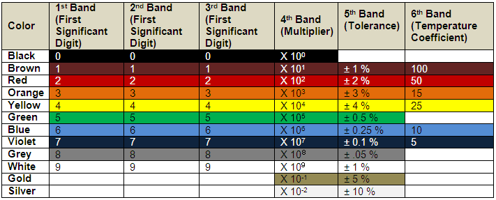
Fig. 1: Table listing color coding for 6-band resistors
Let us assume we have a six band resistance with the following color coding representing first band to last band respectively:
Green Black Blue Brown Gold Red
Step 1: The first color represents the first significant digit. In this case it is 5 corresponding to Green as per the table.
Step 2: The second color represents the second significant digit. In this case it is 0 corresponding to Black as per the table.
Step 3: The third color represents the third significant digit. In this case it is 6 corresponding to Blue as per the table.
So far the value can be represented as 506
Step 4: The fourth color represents the multiplier i.e., it represents the number by which the value formed from the first three digits needs to be multiplied in order to get the value of the resistance. In this case it is 101 = 10 corresponding to Brown as per the table.
Hence the value of the resistance is:
506 x 10= 5060 ohms =5.06K ohm
Step 5: The fifth digit represents the tolerance. The tolerance gives an indication of the extreme variation that can happen in the value of resistance. It is represented as percentage of original value. In this case it is ± 5% corresponding to Gold.
Step 6: The last digit represents the temperature coefficient. The temperature coefficient tells us the change in the value of resistance with temperature. It is generally expressed as ppm/(degree Celcius). In this case it is 50 corresponding to RED.
So the value of resistance in this case comes out to be 5.06K ohm with ± 5% tolerance and 50ppm/degree C.
Note: The value of the colors corresponding to any of the digit which is not given in the table is never used for that particular digit.
Resistor Color Code for 5 color band resistor
Resistor Color Code for five (5) color band resistor
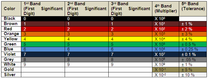
Fig. 2: Table listing color coding for 5-band resistors
Let us assume we have a five band resistance with the following color coding representing first band to last band respectively:
Green Black Blue Brown Gold
Step 1: The first color represents the first significant digit. In this case it is 5 corresponding to Green as per the table.
Step 2: The second color represents the second significant digit. In this case it is 0 corresponding to Black as per the table.
Step 3: The third color represents the third significant digit. In this case it is 6 corresponding to Blue as per the table.
So far the value can be represented as 506
Step 4: The fourth color represents the multiplier i.e., it represents the number by which the value formed from the first three digits needs to be multiplied in order to get the value of the resistance. In this case it is 101 = 10 corresponding to Brown as per the table.
Hence the value of the resistance is:
506 x 10= 5060 ohms =5.06K ohm
Step 5: The fifth digit represents the tolerance. The tolerance gives an indication of the extreme variation that can happen in the value of resistance. It is represented as percentage of original value. In this case it is ± 5% corresponding to Gold.
So the value of resistance in this case comes out to be 5.06K ohm with ± 5% tolerance
Note: The value of the colors corresponding to any of the digit which is not given in the table is never used for that particular digit.
Resistor Color Code for 4 color band resistor
Resistor Color Code for four (4) color band resistor
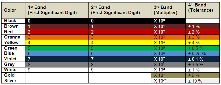
Fig. 3: Table listing color coding for 4-band resistors
Let us assume we have a four band resistance with the following color coding representing first band to last band respectively:
Green Black Blue Gold
Step 1: The first color represents the first significant digit. In this case it is 5 corresponding to Green as per the table.
Step 2: The second color represents the second significant digit. In this case it is 0 corresponding to Black as per the table.
Step 3: The third color represents the multiplier i.e., it represents the number by which the value formed from the first three digits needs to be multiplied in order to get the value of the resistance. In this case it is 106 = 1000000 corresponding to Brown as per the table.
Hence the value of the resistance is:
50 x 106= 50000000 ohms =50M ohm
Step 4: The fourth digit represents the tolerance. The tolerance gives an indication of the extreme variation that can happen in the value of resistance. It is represented as percentage of original value. In this case it is ± 5% corresponding to Gold.
So the value of resistance in this case comes out to be 50M ohm with ± 5% tolerance
Note: The value of the colors corresponding to any of the digit which is not given in the table is never used for that particular digit.
Resistor Color Code for 3 color band resistor
Resistor Color Code for three (3) color band resistor
The color coding scheme for resistances with three color bands is exactly the same as that of four color bands with the difference that the tolerance is 20% by default.
The first color represents the first significant digit, the second color the second significant digit and the third color the multiplier with tolerance of 20%.
You may also like:
Filed Under: Tutorials



Questions related to this article?
👉Ask and discuss on EDAboard.com and Electro-Tech-Online.com forums.
Tell Us What You Think!!
You must be logged in to post a comment.