Engineers Garage

  • Projects and Tutorials
    • Electronic Projects
      • 8051
      • Arduino
      • ARM
      • AVR
      • PIC
      • Raspberry pi
      • STM32
    • Tutorials
    • Circuit Design
    • Project Videos
    • Components
  • Articles
    • Tech Articles
    • Insight
    • Invention Stories
    • How to
    • What Is
  • News
    • Electronic Products News
    • DIY Reviews
    • Guest Post
  • Forums
    • EDABoard.com
    • Electro-Tech-Online
    • EG Forum Archive
  • Digi-Key Store
    • Cables, Wires
    • Connectors, Interconnect
    • Discrete
    • Electromechanical
    • Embedded Computers
    • Enclosures, Hardware, Office
    • Integrated Circuits (ICs)
    • Isolators
    • LED/Optoelectronics
    • Passive
    • Power, Circuit Protection
    • Programmers
    • RF, Wireless
    • Semiconductors
    • Sensors, Transducers
    • Test Products
    • Tools
  • EE Resources
    • DesignFast
    • LEAP Awards
    • Oscilloscope Product Finder
    • White Papers
    • Webinars
  • EE Learning Center
  • Women in Engineering

Reverse Battery Protection Circuit (Part 1/9)

By Diksha

The 21st century belongs to portable devices that are run by batteries. From smartphones and laptops to smart home and office appliances, the new electronics devices are compact in size, more power efficient, loaded with multiple features and run on supply provided by batteries. These electronic devices usually have components like diodes, transistors, capacitors or ICs having such components embedded in them which are polarized in nature. So the electronics circuit of these devices essentially must be provided DC power is a specific polarity.
Any battery has two terminals – Anode and Cathode and current always flows from anode to cathode. Actually, the electrons flow from cathode to anode. But to maintain the definition of current independent of the charge carriers, the direction of conventional current is always taken from Anode or positive terminal to Cathode or Negative terminal.
A lot of devices due to the requirement of the power supply is a specific polarity have a mechanical assembly or the battery design in a way that the battery can be attached in a specific polarity only. But this is not the case with all the devices. There are lots of devices which run on general purpose batteries and the mechanical assembly of the electronics device only have indicators or instructions inscribed to attach the battery in a specific way. Still, the battery can be attached either way with the circuit by human error.
In case if the battery is connected in reverse polarity to a device, it may cause serious damage to the battery as well the electronics device itself. This is not uncommon. Due to reverse connection, the polarized components start slugging due to the reverse voltage across them and the device may get permanently damaged. The reverse polarity can also affect the battery and the reverse connection may explode the battery or it may be possible that after connecting to a circuit in reverse polarity, the battery may no longer hold the charge.
In order to save the life of the battery and the electronics devices as well, it is usually wise to use a reverse battery protection circuit after the battery or before the internal circuitry of any electronics device. A reverse battery protection circuit can also be incorporated in the supply input of the circuit of a device too. The reverse battery protection circuit also saves the electronics circuit by any back current from the battery.
A reverse battery protection circuit can be built using a diode, MOSFET or BJT. In this tutorial, reverse battery protection circuit from each of these components will be designed and tested for power efficiency with different loads. Instead of taking actual circuits as load, different resistances are taken as a load in the experiment. The voltage drop across the protection circuit and current drawn at the load are measured in order test the power efficiency of the protection circuits.
The protection circuit also consumes power from the battery, which results in wastage of the power. So, the protection circuit should consume the least power so that maximum power is output at the load. The power supplied to a load is proportional to the voltage available at the load circuit. This is the voltage left after the voltage drop in the protection circuit, so the voltage drop across the protection circuit will be measured. The voltage drop across the protection circuit should be minimum. Secondly, the current across the load circuit will be measured which will indicate the actual available power to the load circuit. More is the current drawn by the load circuit, more is the power consumed by it.

Components Required

List of components required for Reverse Battery Protection
Fig. 1: List of Components Required for Reverse Battery Protection 

These are the following methods for designing the battery protection circuit –

1. DIODE – 

The simplest way to design a battery protection circuit is by using a diode. A diode conducts current only in one direction and gets open circuited for reverse polarity. So if a diode is connected in series between the battery and the load circuit, it will allow conduction of current only for one polarity. The diode will get forward biased and allow the flow of current in the load circuit only when the Anode of the battery will be connected to the Anode of the diode. If the Cathode of the battery will be connected to the Anode of the diode, the diode will get reverse biased and stop the conduction of current in the load circuit. This will save the load or any device which is connected to the battery. So diode should be connected so that the cathode of the diode is connected at the load circuit and the battery connector is attached to the anode of the diode. The 1N4007 diode can be used for the reverse battery protection. The 1N4007 diode has a voltage drop of around 0.7 V and maximum forward current of 1A.

 Circuit Diagram of IN4007 based Reverse Battery Protection

Fig. 2: Circuit Diagram of IN4007 based Reverse Battery Protection

During the experiment a 3.7 V Li-ion battery is used which can provide 3.3 V supply voltage. A 1N4007 diode is connected in series to the battery such that Anode of the battery is connected to the Anode of the diode. Different load resistances are connected to the battery and diode circuit through switches and the circuit connections are completed by connecting the common ground to the cathode of the battery. 

Prototype of Diode based Reverse Polarity Protection

Fig. 3: Prototype of Diode based Reverse Polarity Protection

So, Input voltage, Vin = 3.3 V, On measuring voltage drop across the diode and current across the load resistances individually, following results are found – 

Table listing voltage drop across 1N4007 diode and load current for different loads

Fig. 4: Table Listing Voltage Drop Across 1N4007 Diode and Load Current for Different Loads

From the above results, it can be analyzed that the diode takes more voltage drop across it as current demand at the output load increases. To reduce the voltage drop, a Schottky diode can be used which has less forward voltage drop as compared to the 1N4007 diode.

Circuit Diagram of 1N5819 based Reverse Battery Protection

Fig. 5: Circuit Diagram of 1N5819 based Reverse Battery Protection

If the 1N4007 diode is replaced with the 1N5819 Schottky diode in the circuit following results are obtained – 

Input voltage, Vin = 3.3V

Table listing voltage drop across 1N5819 diode and load current for different loads
Fig. 6: Table Listing Voltage Drop Across 1N5819 Diode and Load Current for Different Loads 

From the above result, it can be analyzed that the 1N5819 diode will take more voltage drop across it as the current demand increases at the output load. But the forward voltage drop of Schottky diode is less compared to the 1N4007 diode.

Drawbacks of using diode circuit

• A diode has a voltage drop across it so the overall power consumption is increased. It can be said that a part of the power is wasted by the diode.
• The use of diode limits the maximum output current that can be drawn by the load. For example, 1N4007 and 1N5819 allow a maximum forward current of 1A only.

Solution

• The Schottky Diodes with less forward voltage drop can also be used in place of regular diodes. The diode can be selected as per maximum current required by the load. Instead of the diode, the transistor can be as transistors can also be used for switching applications and they have less voltage drop and can handle high load also.

2. Using N-channel MOSFET – BS170

The third way to design protection circuit is by using N-Channel MOSFET. The NMOS conducts current when there is a positive voltage at its Gate terminal. Otherwise, the NMOS remains in an open circuit condition. In MOSFET an intrinsic body diode is present which conducts when it is forward biased. So NMOS can be used as a switching transistor for making reverse battery protection circuit.  The NMOS generally have less ON resistance (rDS). Due to this, it has less voltage drop in the full conducting state. N-MOSFET can also handle the high load as compared to diode or BJT.

Note: The schematics can be found under the “Circuit Diagram” tab.

So when the battery is attached correctly then MOSFET gets turned on. On reversing the battery the gate terminal is low which turns off the MOSFET and load is disconnected from the battery.

Prototype of Reverse Polarity Protection Circuit Using N MOSFET on Breadboard

Fig. 7: Prototype of Reverse Polarity Protection Circuit Using N MOSFET on Breadboard

During the experiment a 3.7 V Li-ion battery is used which can provide 3.3 V supply voltage. A BS170 NMOS is used for reverse battery protection. The load resistances are connected via switches between the Gate terminal and the Drain terminal of the NMOS. The battery is attached to the Gate terminal and the Source terminal of the NMOS. The NMOS conducts only when the anode of the battery is connected to the base of the NMOS. If the cathode of the battery is connected to the base of the NMOS, the NMOS goes in off condition cutting the supply voltage to the load.

So, Input voltage, Vin = 3.3 V, On measuring voltage drop across the transistor and current across the load resistances individually, following results are found –

Table listing Vds and Load Current for different loads

Fig. 8: Table listing Vds and Load Current for different loads

From the above results, it can be analyzed that the BS170 takes more voltage drop across it as current demand increases at the output. But the voltage drop across the NMOS is far less compared to the diode.

Drawback of using nMOSFET

• The MOSFET requires Gate voltage above a threshold level to get ON. This means they will work only for those batteries that can provide voltage above threshold. For example, the BS170 requires minimum 0.8V at Gate to get ON.

Solution

MOSFETs with lower threshold Gate voltage can be used for low capacity batteries.

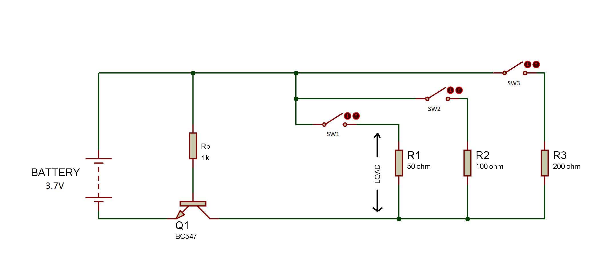
3. Using NPN BJT(bipolar junction transistor) – BC547

Another way of designing Reverse Polarity Protection Circuit is by using BJT Transistors. A BJT can be used as a switching transistor in the circuit for reverse battery protection. The NPN BJT has higher Beta (current gain), that’s why they can be operated at low base current. This reduces the power loss. Also, they have less voltage drop.
Note: The schematics can be found in the “Circuit Diagram 2” tab.

During the experiment, BC547 is used for the reverse battery protection. The transistor is connected in the circuit so that the load circuit is connected between the base and collector of the transistor and the battery is attached to the base and the emitter of the transistor. A pull-up resistor is used at the base of the transistor, so that base could be properly biased. When the battery is attached such that the anode of the battery is connected to the base of the transistor, the forward voltage at the base switches the transistor to ON condition and current starts flowing from collector to the emitter.

This completes the circuit and the load gets the input supply. When the cathode of the battery is connected to the base of the transistor, the base of the transistor is not biased and the transistor switches to the OFF condition. There remains no flow of current between the collector and the emitter of the transistor and the load circuit gets open. This will save the load/device from the reverse current.

Prototype of Reverse Polarity Protection Circuit Using BJT on Breadboard

Fig. 9: Prototype of Reverse Polarity Protection Circuit Using BJT on Breadboard

During the experiment a 3.7 V Li-ion battery is used which can provide 3.3 V supply voltage. A BC547 transistor is connected such that the load resistances are connected between the base and the collector of the transistor and the battery connectors are connected between the base and emitter of the transistor. 

So, Input voltage, Vin = 3.3 V, On measuring voltage drop across the transistor and current across the load resistances individually, following results are found –
Table listing Vce and load current for different loads
Fig. 10: Table Listing Vce and Load Current for Different Loads
From the above results, it can be analyzed that the BC547 takes more voltage drops across it, as current demand increases at the output. But the voltage drop across BJT is far less compared to the diode and the MOSFET. So the BJT works better than MOSFET and the diode as reverse battery protection circuit.

Drawbacks of using BC547

• The circuit should be designed to keep a base current in such a way that it can drive a high load with minimum power loss. This is due to the fact that, the collector current depends on the base current.
• The BC547 allows a maximum current of 100mA through the collector. This limits the maximum current that can be drawn by the load.

Solution

• In some cases, BJT like 2N2222A can be used to solve the current limit problem. The 2N2222A allows the maximum current of 1A.
• MOSFET can be used in place of BJT as MOSFET has lower on-resistance as compared to BJT and can handle high load. But with the use of MOSFET, there have to compromise with power loss as MOSFET has high power loss than BJT.

Conclusion –

On comparing the use of diode, BJT, and MOSFET as reverse battery protection circuit, the results derived are summarized in the following table –
Table listing characterstics of reverse battery protection using diode, NPN BJT and N-MOSFET
Fig. 11: Table Listing Characterstics of Reverse Battery Protection using Diode, NPN BJT and N-MOSFET
So it can be concluded that on using a diode, NMOS and BJT for reverse battery protection, use of BJT is the most power efficient but has current limitation. Alternatively, NMOS can be used but has a threshold voltage issue. So, for load circuits with low current demand, use of BJT is best. If the load circuit has high current demand and operates on high power, use of NMOS is recommended. For low-cost circuits in which voltage drop or current demand is not an issue, a diode can be used.  

Circuit Diagrams

Circuit-Diagram-NPN-BJT-Based-Reverse-Battery-Protection


Filed Under: Electronic Projects


Questions related to this article?
👉Ask and discuss on EDAboard.com and Electro-Tech-Online.com forums.


Tell Us What You Think!! Cancel reply

You must be logged in to post a comment.

HAVE A QUESTION?

Have a technical question about an article or other engineering questions? Check out our engineering forums EDABoard.com and Electro-Tech-Online.com where you can get those questions asked and answered by your peers!


Featured Tutorials

  • Designing Gate Driver Circuit and Switching Mechanism for Modified Sine Wave Inverter – (Part 9/17)
  • Completing Modified Sine Wave Inverter Design with Full Bridge Circuit and Step Up Transformer – (Part 10/17)
  • Designing an Offline UPS – Part (12 /17)
  • How to reduce Switching Time of a Relay – (Part 15/17)
  • Testing MOSFET – (Part 16/17)
  • Driving High Side MOSFET using Bootstrap Circuitry – (Part 17/17)

Stay Up To Date

Newsletter Signup

Sign up and receive our weekly newsletter for latest Tech articles, Electronics Projects, Tutorial series and other insightful tech content.

EE Training Center Classrooms

EE Classrooms

Recent Articles

  • Designing Gate Driver Circuit and Switching Mechanism for Modified Sine Wave Inverter – (Part 9/17)
  • Completing Modified Sine Wave Inverter Design with Full Bridge Circuit and Step Up Transformer – (Part 10/17)
  • Designing an Offline UPS – Part (12 /17)
  • How to reduce Switching Time of a Relay – (Part 15/17)
  • Testing MOSFET – (Part 16/17)

Most Popular

5G 555 timer circuit 8051 ai Arduino atmega16 automotive avr dc motor display Electronic Part Electronic Parts Fujitsu ic infineontechnologies integratedcircuit Intel IoT ir lcd ldr led maximintegratedproducts microchip microchiptechnology Microchip Technology microcontroller microcontrollers mosfet motor powermanagement Raspberry Pi remote renesaselectronics Research robot samsung semiconductor sensor software STMicroelectronics switch Technology vishayintertechnology wireless

RSS EDABOARD.com Discussions

  • Please help to identify the signal input port on board
  • Hotplugging UART
  • RF switch selection
  • sensitivity in filters and number of bits of system
  • MDO4104-6 Front Panel Not Working

RSS Electro-Tech-Online.com Discussions

  • Passthrough charging-simple but impossible to achieve?
  • geared motor to revolve oval platform
  • software PWM
  • None existant errors (MPLAB X)
  • How can a 13 bit number represent 16 bit number?Or why is fragmentation offset multiple of 8?
Engineers Garage
  • Analog IC TIps
  • Connector Tips
  • DesignFast
  • EDABoard Forums
  • EE World Online
  • Electro-Tech-Online Forums
  • Microcontroller Tips
  • Power Electronic Tips
  • Sensor Tips
  • Test and Measurement Tips
  • 5G Technology World
  • About Us
  • Contact Us
  • Advertise

Copyright © 2022 WTWH Media LLC. All Rights Reserved. The material on this site may not be reproduced, distributed, transmitted, cached or otherwise used, except with the prior written permission of WTWH Media
Privacy Policy | Advertising | About Us

Search Engineers Garage

  • Projects and Tutorials
    • Electronic Projects
      • 8051
      • Arduino
      • ARM
      • AVR
      • PIC
      • Raspberry pi
      • STM32
    • Tutorials
    • Circuit Design
    • Project Videos
    • Components
  • Articles
    • Tech Articles
    • Insight
    • Invention Stories
    • How to
    • What Is
  • News
    • Electronic Products News
    • DIY Reviews
    • Guest Post
  • Forums
    • EDABoard.com
    • Electro-Tech-Online
    • EG Forum Archive
  • Digi-Key Store
    • Cables, Wires
    • Connectors, Interconnect
    • Discrete
    • Electromechanical
    • Embedded Computers
    • Enclosures, Hardware, Office
    • Integrated Circuits (ICs)
    • Isolators
    • LED/Optoelectronics
    • Passive
    • Power, Circuit Protection
    • Programmers
    • RF, Wireless
    • Semiconductors
    • Sensors, Transducers
    • Test Products
    • Tools
  • EE Resources
    • DesignFast
    • LEAP Awards
    • Oscilloscope Product Finder
    • White Papers
    • Webinars
  • EE Learning Center
  • Women in Engineering