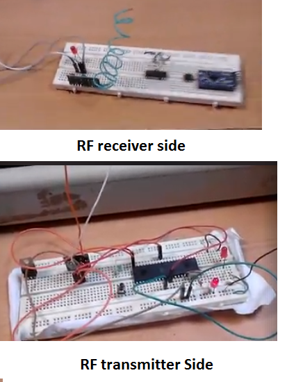
RF transmitter and receiver module – working
Any microcontroller have a serial UART(Universal Asynchronous Receiver-Transmitter) port can be used with RF receiver and transmitter. Both 8051 microcontroller and arduino uno have Uart ports. We can connect RF transmitter to one and RF receiver to another in order to transfer data between both of them.
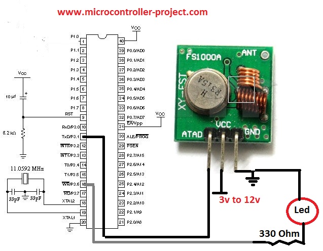
Note: I assume that you are already familiar with the UART(Universal Asynsronous Receiver-Transmitter). If not then first take some tutorials to know about what is UART? and for what purpose it is used? RF(433MHz, 418MHz, 315MHz) Transmitter Circuit Diagram
300 bps is a very low data transmission rate. Tiny RF modules like the one i am using in the tutorial best works on low baud rates. At high baud rates their is a greater chance of data loss during propagating through air. So i also recommend you to use low baud rate when working with tiny short range 433 MHz RF receiver and transmitter.
RF transmission data
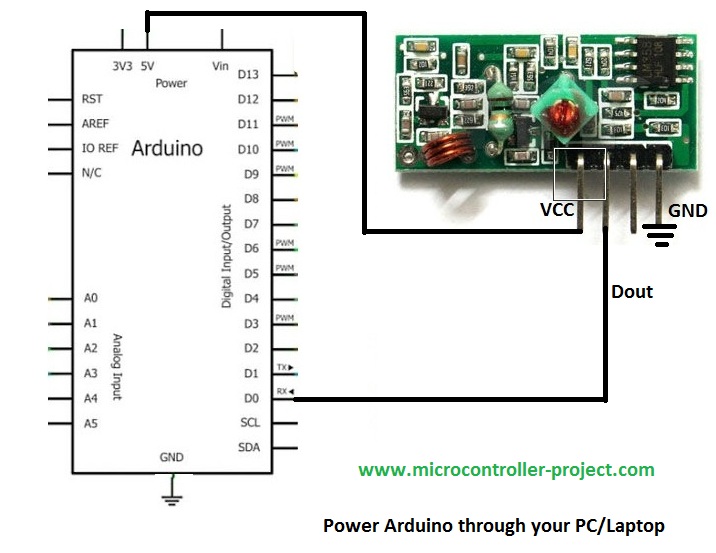
RF(433MHz, 418MHz, 315MHz) Receiver Circuit Diagram
All the RF modules works same. But their pin out from different vendors may differ. Some even have eight pins. Data receive pin is only one on all RF receiver’s irrespective of any manufacturer. Similarly transmit pin is only one on ever RF transmitter irrespective of the manufacturer. The extra pins on RF modules are multiple ground pins. CS chip select pins or interrupts(hardly any) etc.
Note: Serial.read() function reads the value in decimal form. So if ‘U‘ is received, Serial.read() will read its decimal value. we have to convert the decimal value in to its equivalent ASCII character to display it on arduino serial monitor. The statement char b=(a-‘0’)+0x30; is converting the decimal value in to its equivalent ASCII character. Which is then displayed on serial monitor of arduino uno.
Watch the project video Here…..
Filed Under: Arduino, Microcontroller Projects

Questions related to this article?
👉Ask and discuss on Electro-Tech-Online.com and EDAboard.com forums.
Tell Us What You Think!!
You must be logged in to post a comment.