Engineers Garage

  • Electronics Projects and Tutorials
    • Electronic Projects
      • Arduino Projects
      • AVR
      • Raspberry pi
      • ESP8266
      • BeagleBone
      • 8051 Microcontroller
      • ARM
      • PIC Microcontroller
      • STM32
    • Tutorials
      • Audio Electronics
      • Battery Management
      • Brainwave
      • Electric Vehicles
      • EMI/EMC/RFI
      • Hardware Filters
      • IoT tutorials
      • Power Tutorials
      • Python
      • Sensors
      • USB
      • VHDL
    • Circuit Design
    • Project Videos
    • Components
  • Articles
    • Tech Articles
    • Insight
    • Invention Stories
    • How to
    • What Is
  • News
    • Electronic Product News
    • Business News
    • Company/Start-up News
    • DIY Reviews
    • Guest Post
  • Forums
    • EDABoard.com
    • Electro-Tech-Online
    • EG Forum Archive
  • DigiKey Store
    • Cables, Wires
    • Connectors, Interconnect
    • Discrete
    • Electromechanical
    • Embedded Computers
    • Enclosures, Hardware, Office
    • Integrated Circuits (ICs)
    • Isolators
    • LED/Optoelectronics
    • Passive
    • Power, Circuit Protection
    • Programmers
    • RF, Wireless
    • Semiconductors
    • Sensors, Transducers
    • Test Products
    • Tools
  • Learn
    • eBooks/Tech Tips
    • Design Guides
    • Learning Center
    • Tech Toolboxes
    • Webinars & Digital Events
  • Resources
    • Digital Issues
    • EE Training Days
    • LEAP Awards
    • Podcasts
    • Webinars / Digital Events
    • White Papers
    • Engineering Diversity & Inclusion
    • DesignFast
  • Guest Post Guidelines
  • Advertise
  • Subscribe

RF Remote Control using Codec Chip ST14

By Ashutosh Bhatt December 20, 2012

Here to make a IR remote control I am using an ASIC codec chip ST12 where codec means coder decoder. That means same chip is used as encoder at transmitter side and as decoder at receiver side. It’s very nice chip and some of the major features of the chip are

  • Encode / Decode on single chip
  • Built in Oscillator
  • Minimum External Components
  • Wide operating voltage range. (2.0 – 5.5V)
  • Single chip Encoding Decoding Mode
  • 40kHz carrier for infrared transmission medium
  • 18 pin DIP package


The major applications of this chip:

  • Burglar alarm system
  • Smoke and fire alarm system
  • Garage door controllers
  • Car door controllers
  • Car alarm system
  • Security System
  • Cordless telephones
  • Other remote control systems


Because both transmitter and receiver made up of only ST14 codec chip, let us first understand pin diagram, pin function and working of this chip and then go for transmitter and receiver.

Pin diagram: –

Pin Diagram


As shown in above figure its 18 pin chip with DIP. Pals refer the table given below for details

 Pin no

Pin name 

Description 

Function 

 1 to 4

A0 – A3 

address inputs 

to setup an address for the system. each pin can either be connected to 0V or Vcc. cannot be left unconnected 

 5

gnd 

0v input 

connected to circuit ground 

 6 to 13

row-col outx

row-column input or output

at transmitter side in encoder mode works as input (8 switches are connected in 4×2 matrix on 4 rows and 2 columns) and at receiver side in decoder mode works as output (connected to external circuit) 

 14

Vcc 

+V input 

connected with +V of 2 to 5 V 

 15

 mode Rx – Tx

 receiver or trasmitter

high or low logic on this pin decides its operation as transmitter or receiver. if connected to Vcc works as receiver and if connected with Gnd works as transmitter

 18

 Data I/O

data input or output

in encoder mode it sends data and in decoder mode receives data 

 17

 Lat – Mom

 latching or momentary

in decoder mode the output will be either latching or just momentary. if connected with Vcc output will toggle every time and if tied to ground a low-high-low pulse on pins 

 16

 IR – RF

infra red or radio freq 

selects transmission via either IR or RF. if tied to Vcc transmits 40 KHz signals via IR led and if tied to Gnd sends data via suitable RF transmitter   

So now after going through above table one should have complete idea about the operation of this chip as transmitter (encoder) and as receiver (decoder).

Transmitter & Receiver

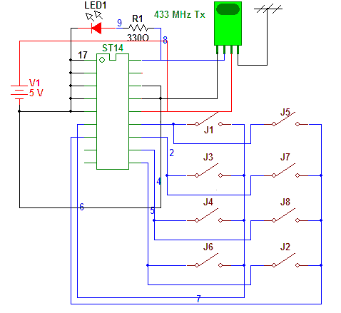
Transmitter: – The major advantage of this chip is that there is least requirement of external components

As shown in Circuit Tab 1 along with ST14 we require 8 push button switches, one LED with current limiting register and an ASK transmitter

Connection: – All four address bits A0 – A3 are shorted to ground to setup an address 0000. 8 push button type switches are connected in row-column (4×2) structure as shown. The transmit data pin drives red LED with 330E resistor and also connected with data i/p of 433 MHz ASK Tx. IR-RF pin is connected to Gnd to configure the chip in RF mode. Mode Rx-Tx pin is also connected with Gnd to configure it as transmitter. A 3V battery (or 2 dry cell) provides power to the circuit.

Operation: – When any of the key is pressed data is transmitted via transmit data pin. The address and data together given to ASK transmitter that will modulate it at 433 MHz freq. This data transmission can be seen on red LED as blinking o/p.

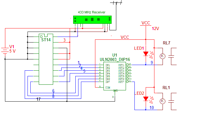
Receiver: – Circuit Diagram tab 2

Connections: – All four address bits A0-A3 are connected to ground to setup same address 0000. Keeping first data o/p D0 unconnected, rest all D1 – D7 are connected to input of ULN chip. Each one output of ULN chip drives one relay and one LED. So total there are seven relays that can switch on / off 7 different devices (instead of ULN2003 if one uses ULN2803 then all 8 data outputs can be used). The mode Rx-Tx pin is connected to Vcc to configure the chip as receiver. The lat-mom pin is tied to Vcc to get toggle output every time. The output of 433 MHz ASK Rx is connected to receive data pin of ST14. Two different regulated supplies 5V and 12 V are used to give power to complete circuit. 

Operation: – The 433 MHz ASK Rx will detect the carrier signal and demodulate the address and data and give it to ST14. On getting valid address and data st14 will latch the data on D0-D7. Because its toggle output every time when same switch is pressed from TX, the relay will switch on / off. Also relay on / off is indicated by respective LED. 


Project Source Code


Circuit Diagrams

RF-remote-control
RF-remote-control-receiver


Filed Under: Electronic Projects
Tagged With: remote, rf, st14
 

Next Article

← Previous Article
Next Article →

Questions related to this article?
👉Ask and discuss on Electro-Tech-Online.com and EDAboard.com forums.


Tell Us What You Think!! Cancel reply

You must be logged in to post a comment.

EE TECH TOOLBOX

“ee
Tech Toolbox: Internet of Things
Explore practical strategies for minimizing attack surfaces, managing memory efficiently, and securing firmware. Download now to ensure your IoT implementations remain secure, efficient, and future-ready.

EE Learning Center

EE Learning Center
“engineers
EXPAND YOUR KNOWLEDGE AND STAY CONNECTED
Get the latest info on technologies, tools and strategies for EE professionals.

HAVE A QUESTION?

Have a technical question about an article or other engineering questions? Check out our engineering forums EDABoard.com and Electro-Tech-Online.com where you can get those questions asked and answered by your peers!


RSS EDABOARD.com Discussions

RSS Electro-Tech-Online.com Discussions

  • Capacitive Touch On The Profile
  • going out on a limb and praying the schematic is correct
  • Easy PC Demo version Schem and Layout program questions
  • nicd charger for li-ion
  • Can't get a small CRT display to focus

Featured -USB Series

  • Controller Chip Selection for Developing USB Enabled Device (Part 6/6)
  • Signal and Encoding of USB System (Part 5/6)
  • USB Requests and Stages of Control Transfer (Part 4/6)
  • USB Descriptors and their Types (Part 3/6)
  • USB Protocol: Types of USB Packets and USB Transfers (Part 2/6)
  • Introduction to USB: Advantages, Disadvantages and Architecture (Part 1/6)

Recent Articles

  • Littelfuse driver achieves less than 1 µA standby current for energy-efficient designs
  • Microchip optimizes power consumption in transceiver-less FPGA design for automotive applications
  • What is an IoT platform and when is one useful?
  • Silanna launches laser driver IC with sub-2 ns FWHM pulse for LiDAR application
  • LEM introduces current sensors with bandwidth up to 2.5 MHz for precision applications

EE ENGINEERING TRAINING DAYS

engineering

Submit a Guest Post

submit a guest post
Engineers Garage
  • Analog IC TIps
  • Connector Tips
  • Battery Power Tips
  • DesignFast
  • EDABoard Forums
  • EE World Online
  • Electro-Tech-Online Forums
  • EV Engineering
  • Microcontroller Tips
  • Power Electronic Tips
  • Sensor Tips
  • Test and Measurement Tips
  • 5G Technology World
  • Subscribe to our newsletter
  • About Us
  • Contact Us
  • Advertise

Copyright © 2025 WTWH Media LLC. All Rights Reserved. The material on this site may not be reproduced, distributed, transmitted, cached or otherwise used, except with the prior written permission of WTWH Media
Privacy Policy

Search Engineers Garage

  • Electronics Projects and Tutorials
    • Electronic Projects
      • Arduino Projects
      • AVR
      • Raspberry pi
      • ESP8266
      • BeagleBone
      • 8051 Microcontroller
      • ARM
      • PIC Microcontroller
      • STM32
    • Tutorials
      • Audio Electronics
      • Battery Management
      • Brainwave
      • Electric Vehicles
      • EMI/EMC/RFI
      • Hardware Filters
      • IoT tutorials
      • Power Tutorials
      • Python
      • Sensors
      • USB
      • VHDL
    • Circuit Design
    • Project Videos
    • Components
  • Articles
    • Tech Articles
    • Insight
    • Invention Stories
    • How to
    • What Is
  • News
    • Electronic Product News
    • Business News
    • Company/Start-up News
    • DIY Reviews
    • Guest Post
  • Forums
    • EDABoard.com
    • Electro-Tech-Online
    • EG Forum Archive
  • DigiKey Store
    • Cables, Wires
    • Connectors, Interconnect
    • Discrete
    • Electromechanical
    • Embedded Computers
    • Enclosures, Hardware, Office
    • Integrated Circuits (ICs)
    • Isolators
    • LED/Optoelectronics
    • Passive
    • Power, Circuit Protection
    • Programmers
    • RF, Wireless
    • Semiconductors
    • Sensors, Transducers
    • Test Products
    • Tools
  • Learn
    • eBooks/Tech Tips
    • Design Guides
    • Learning Center
    • Tech Toolboxes
    • Webinars & Digital Events
  • Resources
    • Digital Issues
    • EE Training Days
    • LEAP Awards
    • Podcasts
    • Webinars / Digital Events
    • White Papers
    • Engineering Diversity & Inclusion
    • DesignFast
  • Guest Post Guidelines
  • Advertise
  • Subscribe