Engineers Garage

  • Projects and Tutorials
    • Electronic Projects
      • 8051
      • Arduino
      • ARM
      • AVR
      • PIC
      • Raspberry pi
      • STM32
    • Tutorials
    • Circuit Design
    • Project Videos
    • Components
  • Articles
    • Tech Articles
    • Insight
    • Invention Stories
    • How to
    • What Is
  • News
    • Electronic Products News
    • DIY Reviews
    • Guest Post
  • Forums
    • EDABoard.com
    • Electro-Tech-Online
    • EG Forum Archive
  • Digi-Key Store
    • Cables, Wires
    • Connectors, Interconnect
    • Discrete
    • Electromechanical
    • Embedded Computers
    • Enclosures, Hardware, Office
    • Integrated Circuits (ICs)
    • Isolators
    • LED/Optoelectronics
    • Passive
    • Power, Circuit Protection
    • Programmers
    • RF, Wireless
    • Semiconductors
    • Sensors, Transducers
    • Test Products
    • Tools
  • EE Resources
    • DesignFast
    • LEAP Awards
    • Oscilloscope Product Finder
    • White Papers
    • Webinars
  • EE Learning Center
    • Design Guides
      • WiFi & the IOT Design Guide
      • Microcontrollers Design Guide
      • State of the Art Inductors Design Guide
  • Women in Engineering

Robo Car Control over WiFi

By Ganesh Selvaraj

This tutorial will teach you how to control a Robo car using any  Wifi enabled device.

Components Required:

1.   ESP 8266  Wifi module
2.   Arduino UNO (or its equivalent)
3.   Motor driver L293D
4.   Chassis
5.   12V DC Geared motors X 2
6.   Wheels X 2
7.   Castor Wheel
8.   Wires
9.   Breadboard
10. Small PCB
11. Male headers
12. Female headers

About ESP8266

ESP 8266 is the latest buzz on internet. It is a Wifi module which is just a bit larger than a 1 Re coin. Well that’s not what it is famous for though. What made it very popular among electronic hobbyist is its unbelievable low cost. I got it just for $5 (~300 Rs.) An Arduino along with a Wifi shield would cost 10 times of what this module costs.

Image showing ESP8266 Wi-Fi Modules

FIg. 1: Image showing ESP8266 Wi-Fi Modules

It can be interfaced with any microcontroller through USART communication, which implies that it just needs the RX and TX pins. Another feather to its hat has been added recently. The developer released the SDK files of the module and hence even the module can be re-programmed and its GPIO pins can be used independently without any additional microcontroller. But that is beyond the scope of this tutorial. We would be using the module along with Arduino UNO.

Making a Breadboard adapter for ESP8266 module:

The problem with the module’s physical feature is that you cannot connect it directly to a breadboard. So I’ve decided to make an adapter which will be used to connect the module onto a breadboard.
These are the parts you would need to make the adapter:

Image showing components required for making breadboard adapter of ESP8266 Modem

Fig. 2: Image showing components required for making breadboard adapter of ESP8266 Modem

Start by soldering the female header onto the PCB. Solder the corner pins first so that the header grips onto the PCB properly. Then solder the remaining 4 pins.

Image showing Breadboard Adapter PCB soldered to fit female header of ESP8266 Modem

Fig. 3: Image showing Breadboard Adapter PCB soldered to fit female header of ESP8266 Modem

Next, place the male headers on the opposite side of the PCB and carefully solder it onto the PCB.

Image showing male header placed on breadboard adapter of ESP8266 Modem

Fig. 4: Image showing male header placed on breadboard adapter of ESP8266 Modem

After soldering, you can remove the black plastic part attached to the male header and start soldering each male pin to its corresponding female pin. In the end you would have something like this:

Image showing male header soldered on breadboard adapter of ESP8266 Modem

Fig. 5: Image showing male header soldered on breadboard adapter of ESP8266 Modem

Once you have this, you can snap it onto a Breadboard happily and attach the ESP 8266 module to it easily.

Here is a detailed video tutorial showing the process: http://youtu.be/GhwmgvcjRaA (Optional)

Image showing Breadboard Adapter of ESP8266 Modem placed on a breadboard

Fig. 6: Image showing Breadboard Adapter of ESP8266 Modem placed on a breadboard

Image showing ESP8266 Wi-Fi Module placed over breadboard

Fig. 7: Image showing ESP8266 Wi-Fi Module placed over breadboard

AT Commands for ESP 8266:

Command

Description

AT+GMR

To know the version of firmware

AT+RST

To Reset module

AT+CWMODE

To set the mode of operation i.e., as Access Point or Station mode or both.

AT+CWLAP

To see the list of APs available

AT+CIPSERVER

To set as server

AT+CIPMUX

To choose between single or multiple connections

AT+CIPSEND

To set the channel number, data length and send data over WiFi

AT+CIPCLOSE

To close the connection

Server on ESP 8266:

We will be sending a web interface (an HTML page) to any device (say a Wifi enabled mobile phone) connected to the Wifi module. The code for the HTML page would be provided by the Arduino. And also, the Arduino would decode the request from the device and control the motors accordingly.
Since the Wifi module can operate as an access point also, we don’t need an extra wireless router for the project.
If you have no idea about HTML pages then head to my “Controlling Appliances over Wifi and Ethernet” project and get to know the basics.
Here is the algorithm to be followed for setting up a server on ESP 8266:

Algorithm:

– Test module using “AT” command
– Set mode of operation using “AT+CWMODE=<mode number>” command
– Set number of connections using command “AT+CIPMUX=<number>”
– Set it as server using the command “AT+CIPSERVER=<mode number>,<port>”
– If GET request received from a browser, then use the command “AT+CIPSEND=<channel number>, <data length>” followed   by the html data you would like to send.
– After completion close the connection using “AT+CIPCLOSE” command.

Hardware Setup:

Gather all the parts shown in the image.

Image showing components required for making robot

Fig. 8: Image showing components required for making robot

Attach the motors to the chassis and then the wheels to the axle.

Image showing DC motor attached metallic frame of robot

Fig. 9: Image showing DC motor attached metallic frame of robot

Use some screws and bolts to attach the castor wheel

Image showing wheels attached to the DC motors on Robot

Fig. 10: Image showing wheels attached to the DC motors on Robot

Image of Caster Wheel attached to the front side of Robot Car

Fig. 11: Image of Caster Wheel attached to the front side of Robot Car

Image of fully assembled Robotic Car

Fig. 12: 

Code Explanation:

– Set pins 8, 9, 10 and 11 as output pins and serial communication with baud rate of 9600 bps.
– Send “AT” command to the module.
– Set the mode of operation as both station and Access Point by using command “AT+CWMODE=3”
– Set the connection mode to multiple connections by sending “AT+CIPMUX=1”
– Set the module in Server mode and use the default port by sending “AT+CIPSERVER=1, 80”
– Enter Infinite loop and check for any incoming requests over  Wifi
– If a request has been made, read the request and store the channel number from where the request originated
– Send the html page code to the stored channel number using commands “AT+CIPSEND=<channel number>, <data length>”   followed by the html code data.
– Close the connection using “AT+CIPCLOSE=<channel number>” and wait for the next request made by the browser.
– If request is received, read it and decode the instruction from request. Take corresponding action on motors. (For example,
if you click “Forward” on the webpage, the Arduino would listen to the request, change to robot’s direction to forward)

Setup Instructions

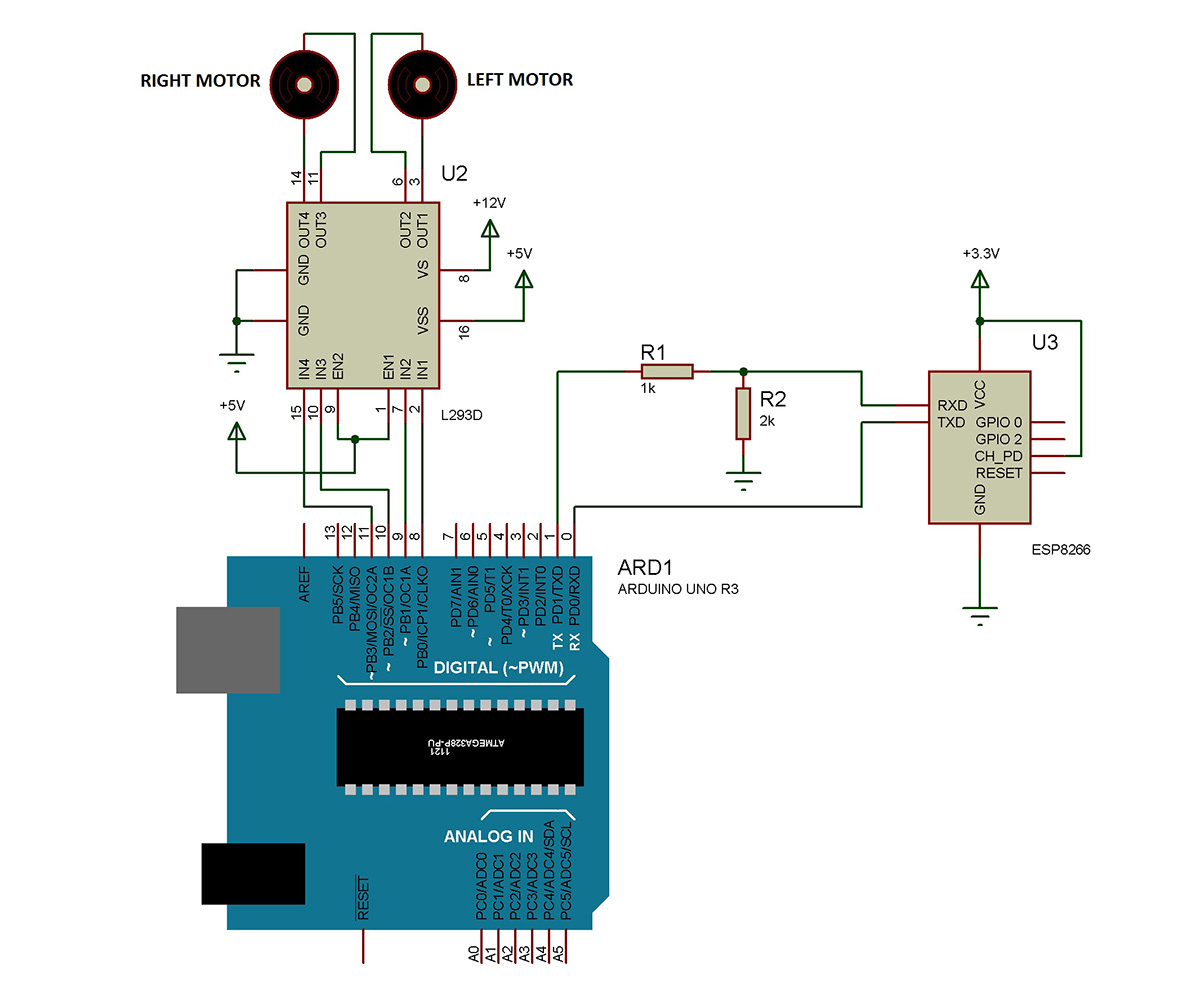
-Connect everything according to the circuit diagram and power on the whole system.

Prototype of simple Robotic Car

Fig. 13: Prototype of simple Robotic Car

– Wait for a few seconds for the Wifi and Arduino to initialize. After 30 seconds or so, enable Wifi on your device (mobile or tablet or laptop) and you should see few available networks.

– You can either connect to your home network (which is “Robots Reloaded” in my case and that’s what I’m going to connect to) or to the Access Point itself (which is “ESP_9F0F14” in my case. The SSID of the module is nothing but it’s name followed by last 6 characters of its MAC Address)

Prototype of Arduino based control circuitry mounted on Robotic Car

Fig. 14: Prototype of Arduino based control circuitry mounted on Robotic Car

– Next, open your browser and dial in the IP address

1. Of the module on the home network in case you are connected to the home network (like me and in my case it’s either 192.168.0.101 or 192.168.0.102)
Or
2. 192.168.1.4 in case you connect to the access point named “ESP_<last 6 characters of MAC Address>”
In a while you should see a page like this in your browser:
Now click the links and you should see the motor start moving. In case they are moving in the wrong direction, check the connections and inter change them if necessary.

Screenshot of Wi-Fi connections on Android Phone showing hotspot from ESP module

Fig. 15: Screenshot of Wi-Fi connections on Android Phone showing hotspot from ESP module

– You can either connect to your home network (which is “Robots Reloaded” in my case and that’s what I’m going to connect to) or to the Access Point itself (which is “ESP_9F0F14” in my case. The SSID of the module is nothing but it’s name followed by last 6 characters of its MAC Address)

Project Source Code

#define esp Serial
 
#define in1 8
#define in2 9
#define in3 10
#define in4 11
#define BUFFER_SIZE 1000
char buffer[BUFFER_SIZE];
 
void send_at(String x)
{
  esp.println(x);
}
 
void setup(){
 
 
pinMode(in1, OUTPUT);
pinMode(in2, OUTPUT);
pinMode(in3, OUTPUT);
pinMode(in4, OUTPUT);
delay(2000);
esp.begin(9600);
esp.println("AT");
delay(1000);
esp.println("AT+CWMODE=3");
delay(1000);
esp.println("AT+CIPMUX=1");
delay(1000);
esp.println("AT+CIPSERVER=1,80");
delay(1000);
esp.println("AT+CIFSR");
delay(1000);
}
 
bool read_till_eol() {
  static int i=0;
  if(esp.available()) {
    char c=esp.read();
    buffer[i++]=c;
    if(i==BUFFER_SIZE)  i=0;
    if(i>1 && buffer[i-2]==13 && buffer[i-1]==10) {
      buffer[i]=0;
      i=0;
      return true;
    }
  }
  return false;
}
 
void loop()
{
  int ch_id, packet_len;
  char *pb;  
  if(read_till_eol()) {
    if(strncmp(buffer, "+IPD,", 5)==0) {
      // request format: +IPD,ch,len:data
      sscanf(buffer+5, "%d,%d", &ch_id, &packet_len);
      if (packet_len > 0) {
        pb = buffer+5;
        while(*pb!=':') pb++;
        pb++;
        if (strncmp(pb, "GET / ", 6) == 0) {
         serve_homepage(ch_id,0);
          }
          else if (strncmp(pb, "GET /?fwd", 9) == 0){
               forward();
               serve_homepage(ch_id,1);
 
           }
          else if (strncmp(pb, "GET /?rev", 9) == 0){
               reverse();
               serve_homepage(ch_id,2);
 
           }
          else if (strncmp(pb, "GET /?rgt", 9) == 0){
               right();
               serve_homepage(ch_id,3);
 
           }
          else if (strncmp(pb, "GET /?lft", 9) == 0){
               left();
               serve_homepage(ch_id,4);
 
           }
          else if (strncmp(pb, "GET /?stp", 9) == 0){
               stop_bot();
               serve_homepage(ch_id,0);
 
           }
    }
  }
}
}
 
void serve_homepage(int ch_id, byte state)
{
          
          delay(1000);
          esp.print(F("AT+CIPSEND="));
          esp.print(ch_id);
          esp.print(",");
          
          esp.println("512");
          delay(500);
 
          esp.print("HTTP/1.1 200 OKrnContent-Type:text/htmlrnrnROBOT CONTROLLER
WELCOME TO THE WEB INTERFACE OF ROBOT CONTROLLER OVER WIFI


");
 
          esp.print("

FORWARD

LEFT    STOP    ");
          esp.print("RIGHT

REVERSE


Created by GANESH SELVARAJ for EngineersGarage.com


");
          delay(5000);
 
          esp.print(F("AT+CIPCLOSE="));
          esp.println(ch_id);
}
 
void forward()
{
  digitalWrite(in1,HIGH);
  digitalWrite(in2,LOW);
  digitalWrite(in3,HIGH);
  digitalWrite(in4,LOW);
}
void reverse()
{
  digitalWrite(in1,LOW);
  digitalWrite(in2,HIGH);
  digitalWrite(in3,LOW);
  digitalWrite(in4,HIGH);
}
void right()
{
  digitalWrite(in1,HIGH);
  digitalWrite(in2,LOW);
  digitalWrite(in3,LOW);
  digitalWrite(in4,LOW);
}
void left()
{
  digitalWrite(in1,LOW);
  digitalWrite(in2,LOW);
  digitalWrite(in3,HIGH);
  digitalWrite(in4,LOW);
}
void stop_bot()
{
  digitalWrite(in1,LOW);
  digitalWrite(in2,LOW);
  digitalWrite(in3,LOW);
  digitalWrite(in4,LOW);
}

Circuit Diagrams

Circuit-Diagram-Arduino-ESP8266-Module-ased-Wi-Fi-Controlled-Robotic-Car

Project Video


Filed Under: Electronic Projects


Questions related to this article?
👉Ask and discuss on EDAboard.com and Electro-Tech-Online.com forums.


Tell Us What You Think!! Cancel reply

You must be logged in to post a comment.

HAVE A QUESTION?

Have a technical question about an article or other engineering questions? Check out our engineering forums EDABoard.com and Electro-Tech-Online.com where you can get those questions asked and answered by your peers!


Featured Tutorials

  • Introduction to Brain Waves & its Types (Part 1/13)
  • Understanding NeuroSky EEG Chip in Detail (Part 2/13)
  • Performing Experiments with Brainwaves (Part 3/13)
  • Amplification of EEG Signal and Interfacing with Arduino (Part 4/13)
  • Controlling Led brightness using Meditation and attention level (Part 5/13)
  • Control Motor’s Speed using Meditation and Attention Level of Brain (Part 6/13)

Stay Up To Date

Newsletter Signup

Sign up and receive our weekly newsletter for latest Tech articles, Electronics Projects, Tutorial series and other insightful tech content.

EE Training Center Classrooms

EE Classrooms

Recent Articles

  • What are the battery-selection criteria for low-power design?
  • Key factors to optimize power consumption in an embedded device
  • EdgeLock A5000 Secure Authenticator
  • How to interface a DS18B20 temperature sensor with MicroPython’s Onewire driver
  • Introduction to Brain Waves & its Types (Part 1/13)

Most Popular

5G 555 timer circuit 8051 ai Arduino atmega16 automotive avr bluetooth dc motor display Electronic Part Electronic Parts Fujitsu ic infineontechnologies integratedcircuit Intel IoT ir lcd led maximintegratedproducts microchip microchiptechnology Microchip Technology microcontroller microcontrollers mosfet motor powermanagement Raspberry Pi remote renesaselectronics renesaselectronicscorporation Research samsung semiconductor sensor software STMicroelectronics switch Technology vishayintertechnology wireless

RSS EDABOARD.com Discussions

  • Band Pass Filte
  • Making a ducted soldering fan?
  • Slope compensation ramp calculation for UCC38084
  • Timer MC14541B wrong delay
  • Pull up via GPIO

RSS Electro-Tech-Online.com Discussions

  • Best way to reduce voltage in higher wattage system?
  • Need a ducted soldering fan for solder smoke extraction
  • Power failure relay options
  • DIY bluetooth speaker
  • Turn CD4029 on/off with TTP223
Engineers Garage
  • Analog IC TIps
  • Connector Tips
  • DesignFast
  • EDABoard Forums
  • EE World Online
  • Electro-Tech-Online Forums
  • Microcontroller Tips
  • Power Electronic Tips
  • Sensor Tips
  • Test and Measurement Tips
  • 5G Technology World
  • About Us
  • Contact Us
  • Advertise

Copyright © 2022 WTWH Media LLC. All Rights Reserved. The material on this site may not be reproduced, distributed, transmitted, cached or otherwise used, except with the prior written permission of WTWH Media
Privacy Policy | Advertising | About Us

Search Engineers Garage

  • Projects and Tutorials
    • Electronic Projects
      • 8051
      • Arduino
      • ARM
      • AVR
      • PIC
      • Raspberry pi
      • STM32
    • Tutorials
    • Circuit Design
    • Project Videos
    • Components
  • Articles
    • Tech Articles
    • Insight
    • Invention Stories
    • How to
    • What Is
  • News
    • Electronic Products News
    • DIY Reviews
    • Guest Post
  • Forums
    • EDABoard.com
    • Electro-Tech-Online
    • EG Forum Archive
  • Digi-Key Store
    • Cables, Wires
    • Connectors, Interconnect
    • Discrete
    • Electromechanical
    • Embedded Computers
    • Enclosures, Hardware, Office
    • Integrated Circuits (ICs)
    • Isolators
    • LED/Optoelectronics
    • Passive
    • Power, Circuit Protection
    • Programmers
    • RF, Wireless
    • Semiconductors
    • Sensors, Transducers
    • Test Products
    • Tools
  • EE Resources
    • DesignFast
    • LEAP Awards
    • Oscilloscope Product Finder
    • White Papers
    • Webinars
  • EE Learning Center
    • Design Guides
      • WiFi & the IOT Design Guide
      • Microcontrollers Design Guide
      • State of the Art Inductors Design Guide
  • Women in Engineering