Engineers Garage

  • Projects and Tutorials
    • Electronic Projects
      • 8051
      • Arduino
      • ARM
      • AVR
      • PIC
      • Raspberry pi
      • STM32
    • Tutorials
    • Circuit Design
    • Project Videos
    • Components
  • Articles
    • Tech Articles
    • Insight
    • Invention Stories
    • How to
    • What Is
  • News
    • Electronic Products News
    • DIY Reviews
    • Guest Post
  • Forums
    • EDABoard.com
    • Electro-Tech-Online
    • EG Forum Archive
  • Digi-Key Store
    • Cables, Wires
    • Connectors, Interconnect
    • Discrete
    • Electromechanical
    • Embedded Computers
    • Enclosures, Hardware, Office
    • Integrated Circuits (ICs)
    • Isolators
    • LED/Optoelectronics
    • Passive
    • Power, Circuit Protection
    • Programmers
    • RF, Wireless
    • Semiconductors
    • Sensors, Transducers
    • Test Products
    • Tools
  • EE Resources
    • DesignFast
    • LEAP Awards
    • Oscilloscope Product Finder
    • White Papers
    • Webinars
  • EE Learning Center
    • Design Guides
      • WiFi & the IOT Design Guide
      • Microcontrollers Design Guide
      • State of the Art Inductors Design Guide
  • Women in Engineering

Rohde & Schwarz updates its 5G MIMO base-station testing solution

By Michelle Froese

The latest software update to the R&S PWC200 plane wave converter (PWC) increases measurement accuracy and refines usability thanks to a new calibration method. With these updates, Rohde & Schwarz extends the possible use cases of its innovative 5G massive MIMO base-station testing solution in R&D, quality assurance, production, and conformance testing.

While the software will be preinstalled in new units, existing R&S PWC200 units can also be upgraded.

The level of integration of 5G base stations in the FR1 frequency range is increasing, as a new generation of base stations, designated the 1-O type, is becoming more common. The 1-O type base stations operate at FR1 frequency range and they have antenna arrays with integrated transceivers, without any access to internal RF ports. This requires all conformance and production testing to be performed over-the-air (OTA). However, OTA testing can be technically challenging.

For accurate OTA measurements, signal waves sent from the antenna must be plane when reaching the device under test (DUT). The area encompassing the DUT where the waves are plane is called the quiet zone (QZ). This can be achieved through a large distance between the antenna and the DUT, resulting in large and expensive shielding chambers.

Rohde & Schwarz has a strong portfolio of solutions for OTA testing, designed to answer these challenges. Some of them are based on compact antenna test range (CATR) technology, where a gold-plated reflector is used to create the plane waves, allowing the DUT to be relatively close to the antenna. However, with large DUTs such as base stations, the size of the high-precision mirror would be prohibitively large and increase the price of the system considerably.

With a solution based on the PWC technology in its OTA test portfolio, Rohde & Schwarz is broadening the options available to the users, especially for large DUTs.

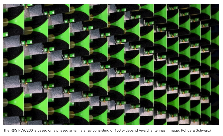
The R&S PWC200 requires four times less space than solutions based on other OTA technologies such as CATR. The R&S PWC200 is based on a phased antenna array consisting of 156 wideband Vivaldi antennas to form plane waves within an adjustable QZ, placed in the radiating near field of the DUT. It functions as a planar-wave synthesizer and near-field scanner and is designed for 5G massive MIMO base-station testing for real-time radiated power and transceiver measurements (EVM, ACLR, SEM, etc.) in a controlled anechoic test chamber environment.

The R&S PWC200 features an internal RF verification solution. This makes it possible to perform precise monitoring and correction of the R&S PWC200 antenna without using an external antenna.

Released originally two years ago, the R&S PWC200 was the first PWC-based solution on the market. It has been accepted as OTA base-station measurement methodology by 3GPP in the conformance test specifications for NR (3GPP TS 38.141-2) and advanced antenna system (AAS) for LTE and WCDMA (3GPP TS 37.145-2).

The latest updates improve several aspects of the solution. As the 5G frequency bands vary from country to country, the original frequency range of the R&S PWC200 from 2.3 GHz to 3.8 GHz was extended to now cover 1.7 GHz to 5 GHz. This increases applications for users worldwide. Additionally, thanks to a novel approach to the PWC calibration the accuracy of the plane wave synthesis has been increased even further. This results in three times better accuracy in magnitude and phase uniformity compared to the previous solution.

“Our creative and enthusiastic development team completely redefined the calibration procedure of the R&S PWC200. Consequently, we are able to offer our customers the opportunity of testing their new generation base-station products with the lowest possible measurement uncertainty and the maximum usability of a PWC test system,” said Dr. Adam Tankielun, senior development expert, Antenna Test Systems, with Rohde & Schwarz. “And they get a turnkey solution from a single vendor, complete with full support and service that can be tailored to their needs.”


Filed Under: News, Uncategorized
Tagged With: rohde&schwarz
 

Questions related to this article?
👉Ask and discuss on Electro-Tech-Online.com and EDAboard.com forums.


Tell Us What You Think!! Cancel reply

You must be logged in to post a comment.

HAVE A QUESTION?

Have a technical question about an article or other engineering questions? Check out our engineering forums EDABoard.com and Electro-Tech-Online.com where you can get those questions asked and answered by your peers!


Featured Tutorials

  • PS2 Keyboard To Store Text In SD Card Using Arduino Circuit Setup On Breadboard
    How To Use PS2 Keyboard To Store Text In SD Card Using Arduino- (Part 42/49)
  • Wireless Path Tracking System Using Mouse, XBee And Arduino Circuit Setup On Breadboard
    How To Make A Wireless Path Tracking System Using Mouse, XBee And Arduino- (Part 43/49)
  • How to Make a Wireless Keyboard Using Xbee with Arduino- (Part 44/49)
  • Making Phone Call From GSM Module Using Arduino Circuit Setup On Breadboard
    How to Make Phonecall From GSM Module Using Arduino- (Part 45/49)
  • How to Make a Call using Keyboard, GSM Module and Arduino
    How To Make A Call Using Keyboard, GSM Module And Arduino- (Part 46/49)
  • Receiving SMS Using GSM Module With Arduino Prototype
    How to Receive SMS Using GSM Module with Arduino- (Part 47/49)

Stay Up To Date

Newsletter Signup

Sign up and receive our weekly newsletter for latest Tech articles, Electronics Projects, Tutorial series and other insightful tech content.

EE Training Center Classrooms

EE Classrooms

Recent Articles

  • How to interface a DS18B20 temperature sensor with MicroPython’s Onewire driver
  • What is a low power design?
  • Renesas partners with Tata to accelerate progress in advanced electronics
  • STMicroelectronics’ new touchscreen controller for smartphones enables longer runtime
  • Samsung unveils ISOCELL image sensor with industry’s smallest 0.56μm pixel

Most Popular

5G 555 timer circuit 8051 ai Arduino atmega16 automotive avr bluetooth dc motor display Electronic Part Electronic Parts Fujitsu ic infineontechnologies integratedcircuit Intel IoT ir lcd led maximintegratedproducts microchip microchiptechnology Microchip Technology microcontroller microcontrollers mosfet motor powermanagement Raspberry Pi remote renesaselectronics renesaselectronicscorporation Research samsung semiconductor sensor software STMicroelectronics switch Technology vishayintertechnology wireless

RSS EDABOARD.com Discussions

  • How do you find the angle made by two isosceles triangles in a kite?
  • MWO - EM Structure missing
  • Effect of variable gain amplifier and LNA on the input RF signal's phase
  • HF preamplifier with threshold?
  • Does Monostable pulse stay HIGH whilst input pulse is HIGH?

RSS Electro-Tech-Online.com Discussions

  • Help wanted to power an AC120v induction motor ( edited from Brushless motor - thank you @SHORTBUS= )
  • NOR gate oscillator in LTspice not working
  • HELP NEEDED
  • intro to PI
  • Lighting a .010 green fiber optic with led
Engineers Garage
  • Analog IC TIps
  • Connector Tips
  • DesignFast
  • EDABoard Forums
  • EE World Online
  • Electro-Tech-Online Forums
  • Microcontroller Tips
  • Power Electronic Tips
  • Sensor Tips
  • Test and Measurement Tips
  • 5G Technology World
  • About Us
  • Contact Us
  • Advertise

Copyright © 2022 WTWH Media LLC. All Rights Reserved. The material on this site may not be reproduced, distributed, transmitted, cached or otherwise used, except with the prior written permission of WTWH Media
Privacy Policy | Advertising | About Us

Search Engineers Garage

  • Projects and Tutorials
    • Electronic Projects
      • 8051
      • Arduino
      • ARM
      • AVR
      • PIC
      • Raspberry pi
      • STM32
    • Tutorials
    • Circuit Design
    • Project Videos
    • Components
  • Articles
    • Tech Articles
    • Insight
    • Invention Stories
    • How to
    • What Is
  • News
    • Electronic Products News
    • DIY Reviews
    • Guest Post
  • Forums
    • EDABoard.com
    • Electro-Tech-Online
    • EG Forum Archive
  • Digi-Key Store
    • Cables, Wires
    • Connectors, Interconnect
    • Discrete
    • Electromechanical
    • Embedded Computers
    • Enclosures, Hardware, Office
    • Integrated Circuits (ICs)
    • Isolators
    • LED/Optoelectronics
    • Passive
    • Power, Circuit Protection
    • Programmers
    • RF, Wireless
    • Semiconductors
    • Sensors, Transducers
    • Test Products
    • Tools
  • EE Resources
    • DesignFast
    • LEAP Awards
    • Oscilloscope Product Finder
    • White Papers
    • Webinars
  • EE Learning Center
    • Design Guides
      • WiFi & the IOT Design Guide
      • Microcontrollers Design Guide
      • State of the Art Inductors Design Guide
  • Women in Engineering