RTC based device ON-OFF timer means it will turn ON and OFF the device at the required time. It will turn ON the device at selected time and again after the preset time, it will turn it OFF also. So, the device turns ON and turns OFF operation because automatic as per preset time schedule.
Such devices are widely used in industries. In industries, it is required to turn ON and OFF the device at a specific time. If the devices are operated for a specific time period with accurate timings then there can be less power consumption and this will directly reduce the production cost. Many industries appoint human operators to operate the device for desired time duration. But this is not a good choice as there may be a lack of accuracy.

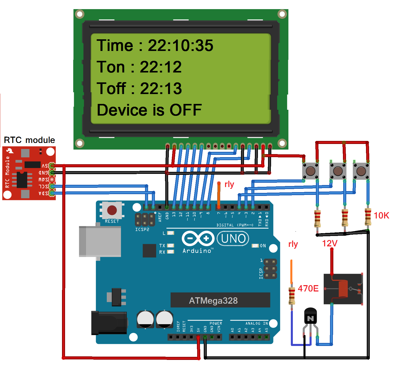
Fig. 1: Prototype of Arduino and RTC DS1307 based Device ON-OFF Timer
One of the examples of this system is time operated automatic water pump and valve. They are widely used in modern farms, gardens, golf courses, greenhouses and other such places. Every day the water pump starts at a specific time and all the valves also turn ON at a specific time interval. Again after preset time interval valves and the motor pump shuts OFF automatically. This is completely automatic daily routine.
Here, the given project demonstrates one such device ON-OFF timer that is RTC – real time clock enabled. It turns ON and OFF any 230V AC operated the device (or maybe 12V or 24 V DC operated device) as per preset time. It is equipped with RTC chip DS1307 and uses Arduino. It has also LCD panel to display clock (time) device ON and OFF timings and other messages. So let’s see how we can build such project. First, go through the circuit diagram followed by its description and operation
Circuit description:
As shown in above figure the circuit is build using RTC DS1307 chip module, 16×4 LCD and few other components like pushbuttons, relay, transistors, resistors, etc.
• RTC module has four wire interface Vcc, Gnd, SDA, and SCL. Vcc and Gnd pins are connected to arduino board 5 V and Gnd respectively that gives it biasing voltage for its operation.
• SCL and SDA pins are connected to arduino SCL and SDA pins. Arduino communicates with RTC DS1307 using these two pins.
• Three push buttons are connected to arduino digital pins 2, 3 and 4. All three push buttons are pulled down to ground through 10 K resistors as shown. when any button is pressed, the respective arduino pin gets logic 1 (HIGH) input.
• Digital pin 7 drives 12 V relay through NPN type transistor. The relay coil is connected to the collector of the transistor.
• The device (not shown in the figure) is connected to relay contact terminals. Means the device is turned ON when the relay is turned ON.
• Data pins D4-D7 of LCD are connected to arduino pins 10 – 13. Two control pins Rs and En are connected to pins 8 and 9 respectively. Control pins RW and VEE (contras control) are connected to ground.
• Backlight LED of LCD is given 5V supply.
Circuit operation:
• When the power is given to circuit through USB, initially the relay and device is OFF. The person has to first set device turn ON time and device OFF time.
• The initial message is displayed on LCD as “Set Device ON time”
• Now a person has to set device turn ON time using push buttons. The 3 push buttons have following functions:
Button Function
Button 1 Increment hour from 0 to 23
Button 2 Increment minute from 0 to 59
Button 3 Set and enter selected time
• So by pressing button 1 and button 2, the person will set require hour and minute and then press enter button to set device ON time
• The message is displayed on LCD as “The device ON time is set to XX:XX:XX ”
• Similarly, the person has to set device OFF time. When device off time is set again the message is displayed on LCD as “The device OFF time is set to XX:XX:XX ”
• After 2 seconds, the actual circuit operation starts
• Arduino reads current time from RTC module and displays it on LCD as “Time:- XX:XX:XX”
• Along with this LCD also displays set (entered) device ON time and device OFF time as Ton and Toff
• It continuously checks if the current time is and device ON time are same. When they match, it turns ON the relay and so the device by sending HIGH logic (1) on digital pin 7
• The message displayed on LCD as “Device is ON”
• Now when the current time equals device off time, the device is turned OFF by turning OFF the relay. The message displayed on LCD as “Device is OFF”
Program:
Project Source Code
###
//Program to#include <Wire.h> #include "RTClib.h" #include <LiquidCrystal.h> #include<EEPROM.h> #define set_hr 2 #define set_min 3 #define ent 4 #define device 7 // initialize the library with the numbers of the interface pins LiquidCrystal lcd(8, 9, 10, 11, 12, 13); RTC_DS1307 rtc; int hr=0, minut=0,ton_flag=1,toff_flag=0,ton_hr,ton_min, toff_hr, toff_min,sys_en_flag=0; void setup () { //while (!Serial); Serial.begin(9600); lcd.begin(16, 4); lcd.clear(); lcd.setCursor(0,0); lcd.print("Set Device ON "); lcd.setCursor(0,1); lcd.print("Time:"); lcd.setCursor(0,2); lcd.print("00:00:00"); if (! rtc.begin()) { Serial.println("Couldn't find RTC"); while (1); } if (! rtc.isrunning()) { Serial.println("RTC is NOT running!"); } pinMode(set_hr,INPUT); pinMode(set_min,INPUT); pinMode(ent,INPUT); pinMode(device,OUTPUT); digitalWrite(device,LOW); } void loop () { int hr_set_but,min_set_but,ent_but; hr_set_but = digitalRead(set_hr); min_set_but = digitalRead(set_min); ent_but = digitalRead(ent); ///////////////// turn device ON or OFF ////////////////////////////// if(sys_en_flag) { DateTime now = rtc.now(); //////////////////// display current time on LCD //////////////// lcd.setCursor(6,0); lcd.print(" "); lcd.setCursor(6,0); lcd.print(now.hour()); lcd.print(':'); lcd.print(now.minute()); lcd.print(':'); lcd.print(now.second()); if(now.hour()==EEPROM.read(11) && now.minute()==EEPROM.read(12)) { digitalWrite(device,HIGH); lcd.setCursor(0,3); lcd.print("Device is ON"); } if(now.hour()==EEPROM.read(13) && now.minute()==EEPROM.read(14)) { digitalWrite(device,LOW); lcd.setCursor(0,3); lcd.print("Device is OFF"); } delay(1000); } //////////////////////// set ON time and OFF time for device ///////// if(hr_set_but) { if(hr<24) hr++; if(hr==24) hr=0; lcd.setCursor(0,2); lcd.print(" "); lcd.setCursor(0,2); lcd.print(hr); delay(200); } if(min_set_but) { if(minut<60) minut++; if(minut==60) minut=0; lcd.setCursor(3,2); lcd.print(" "); lcd.setCursor(3,2); lcd.print(minut); delay(200); } if(ent_but) { if(ton_flag==1) { ton_hr=hr; ton_min = minut; EEPROM.write(11,ton_hr); EEPROM.write(12,ton_min); ton_flag=0; toff_flag=1; lcd.setCursor(0,0); lcd.print("device ON time "); lcd.setCursor(0,1); lcd.print("is set to"); lcd.setCursor(0,2); lcd.print(ton_hr); lcd.print(':'); lcd.print(ton_min); delay(2000); lcd.setCursor(0,0); lcd.print("Set Device OFF "); lcd.setCursor(0,1); lcd.print("Time: "); lcd.setCursor(0,2); lcd.print("00:00:00"); hr = 0; minut = 0; } else if(toff_flag==1) { toff_hr=hr; toff_min = minut; EEPROM.write(13,toff_hr); EEPROM.write(14,toff_min); lcd.setCursor(0,0); lcd.print("device OFF time "); lcd.setCursor(0,1); lcd.print("is set to"); lcd.setCursor(0,2); lcd.print(toff_hr); lcd.print(':'); lcd.print(toff_min); delay(2000); lcd.clear(); lcd.setCursor(0,0); lcd.print("Time: "); lcd.setCursor(0,1); lcd.print("Ton: "); lcd.print(ton_hr); lcd.print(':'); lcd.print(ton_min); lcd.setCursor(0,2); lcd.print("Toff: "); lcd.print(toff_hr); lcd.print(':'); lcd.print(toff_min); sys_en_flag=1; } } }###
Circuit Diagrams
Filed Under: Electronic Projects

Questions related to this article?
👉Ask and discuss on Electro-Tech-Online.com and EDAboard.com forums.
Tell Us What You Think!!
You must be logged in to post a comment.