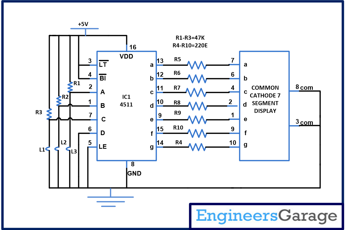
You can easily install this security system in your homes or offices doors to prevent the entry of un-authorized person. This simple circuit is based on wire loop concept. You can install the wire loop approx. two feet above the ground so that when person enters loop will break and you will come to know. This circuit can be simultaneously fitted in three doors and display the door number on seven segment display whose loop has been broken. If loop of first door is broken it will display 1 and if loop of first and second door both is broken than it will display the sum that is 3. So you can easily understand where stranger is for example if all the door are open it will display 7 (1+2+4).
Circuit is based on CD4511 IC. CD4511 is a CMOS BCD to seven segment latch/decoder. This IC provides the facility of 4-bit storage latch, an 8421 BCD-to-seven segment decoder. It also provides you the of facility lamp test (). It is used to check that all segments of 7 segments are working properly or not. For testing momentarily make the pin low, in short used to test the display.

Pin Diagram Of CD4511 IC and 7 Segment Display
Blanking input () is use to turn off or vary the brightness of the display. Latch enable (LE) is used to store BCD codes. CD4511 is used in various applications like in clock, watches, computer, calculators etc.
When all the loops are intact, display will show 0 indicating that no loop is broken. When loop one is broken, display will indicate 1 and if 1 and 4 is broken display will indicate 5 (sum of 1+4). In this way user can came to know on which door intruder is and they can take safety measurement.
Circuit Diagrams
Project Components
Project Video
Filed Under: Electronic Projects
Filed Under: Electronic Projects


Questions related to this article?
👉Ask and discuss on EDAboard.com and Electro-Tech-Online.com forums.
Tell Us What You Think!!
You must be logged in to post a comment.