Though nodemcu is a wifi module but some times it is required to send an sms with a WiFi application. An IOT trigger or event may require us to send an sms. In this project i am going to show how to send an sms with nodemcu WiFi module. To send an sms we need a GSM module. I chose popular sim900 GSM module for this project. I am going to send a simple raw message on my cell number.
Sim900 communicates with external controller on UART interface. Default baud rate for communication is 9600 bps. But it can went up to 115200 bps. SIM900 gsm utilizes AT commands for it configuration and working. There are plenty of commands but i am going to discuss only few which i used in the project.
Sim900 communicates with external controller on UART interface. Default baud rate for communication is 9600 bps. But it can went up to 115200 bps. SIM900 gsm utilizes AT commands for it configuration and working. There are plenty of commands but i am going to discuss only few which i used in the project.
- AT —This command replies back the status of the GSM module. If ready it sends back “OK”. If not it sends back “Error”.
- AT+CMGF=1 — Sets GSM module in SMS text mode.
- AT+CMGS= “Cell Number” — Enter the cell number whom you want to send sms. Include the Cell number in double quotes.
- After this write your text message.
- Then press CTRL+Z together to send sms. Since we are sending message through plan code. So for CTRL+Z combined key we need its code which is 26(Decimal) or 0x1A(Hexadecimal). It will be later discussed in code.
Power considerations
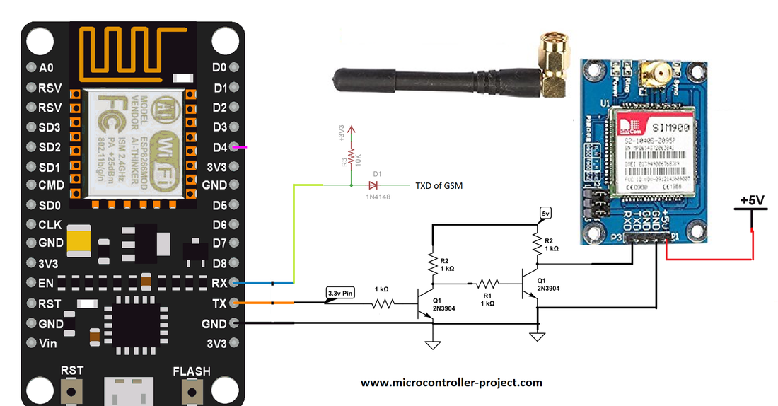
Nopemcu works on 3.3 volts. Where as sim900 module works on 5 volt power supply. Since both the modules work on different TTL levels there for commands and messages from each module first must be converted to receiver operational TTL level before reaching them. TX pin of nodemcu sends signals out at 3.3v TTL level. The 3.3v TTL signal is converted to 5v TTL signal before reaching sim900 module. First transistor converts the TX signal to 5 volt output but the output is inverted. Inverted output is input to second transistor. Which converts the inverted output to original signal with TTL level up to 5v. The output TTL signal is received by the RX pin of sim900 module. Tx of sim900 is connected to Rx of nodemcu with level simple level shifter circuit in between. Project circuit diagram is below.
Sim900 module comes in many variations. Almost all the boards uses the same SIMCOM sim900 chip, only there may be pin out difference. But all communicate on UART interface. So you can use any sim900 board for this project, connections are same for each board.
Note: Sim900 module consumes 500mA of current while sending sms. So please be sure your power supply can supply this amount of current at 5 volts constantly. If your module resets during sending sms than its a clear indication that your module is not getting enough power to send sms out.
Note: Sim900 module consumes 500mA of current while sending sms. So please be sure your power supply can supply this amount of current at 5 volts constantly. If your module resets during sending sms than its a clear indication that your module is not getting enough power to send sms out.
Serial uart channel-0 of nodemcu is used for inter nodemcu and sim900 communication. Communication is carried out at 9600 bps. Arduino ide is used for writing and compiling code. In the setup function serial channel is initialized. In loop function AT commands are send to gsm. Note the format of cell number to which sms is required to be send. At the end of the loop function while(1) function holds the control for ever. If while(1) is not present there loop function will continuously run and sms will be send to receiver continuously. Fou further modifications one can insert a button in circuit and when ever the button is pressed sms will be send out OR one can utilize the WiFi of nodemcu esp8266-12e chip and when ever a certain condition is meet over WiFi, nodemcu triggers sim900 and it shots out an sms.
Download the project code. Folder contains project .ino file. Please give us your valuable feedback on the project. If you have any questions or queries write them below in the comments section.
Filed Under: ESP8266., Microcontroller Projects


Questions related to this article?
👉Ask and discuss on Electro-Tech-Online.com and EDAboard.com forums.
Tell Us What You Think!!
You must be logged in to post a comment.