GSM is quite a common Device which is used in major Projects and Real Time Operations. There are many applications which are using features of GSM Module like the feature sending Messages , making a Voice Call, Receiving Messages, attempting Call etc. Many at times you may have sent Messages using your Cell Phone and also by way of Hyper Terminal of your computer via GSM, and by sending Commands to GSM using Microcontroller.It is assumed that the reader has gone through the project how to get started with the arduino and done all the things discussed in it.
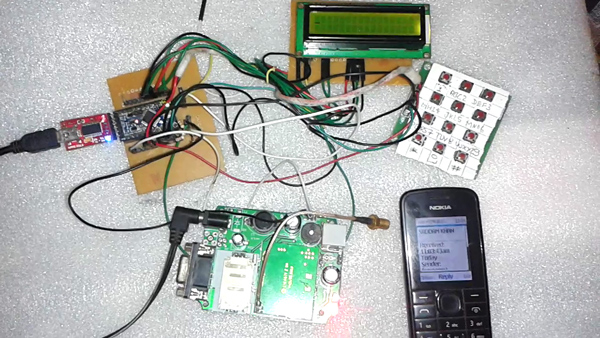
Fig. 1: Prototype of Arduino and GSM GPRS Module based SMS Messaging System
In this project we are going to see how to send a Message using Alpha / Numeric Keypad and GSM. The Programming of this project is little complicated but do not worry, I am sure with careful attention you can build it without any problems.For better understanding the keypad interface reader can read how to interface keypad with arduino.
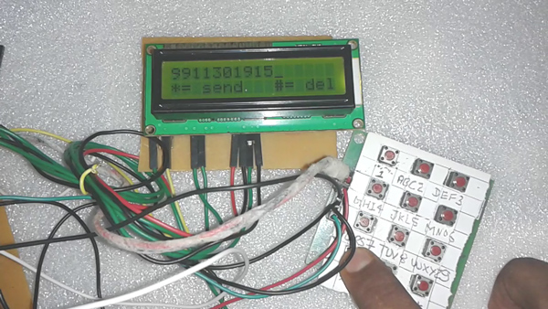
Fig. 2: Image of Character LCD and Alphanumeric Keypad used in SMS Messaging System
As shown in the image above I have used 16×2 LCD Display with arduino which is connected to the numeric keypad. This numeric keypad has been built ingeniously by using keypad circuit having push buttons. For your convenience I have made the cut-out of the typical numeric keypad. So as you can see I have pressed * Button for sending messages
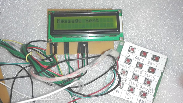
Fig. 3: Image of Character LCD showing status for sent SMS
As you can see in the image above after pressing the * Button for sending message the 16X2 LCD displays the message as sent, and the GSM cell phone receives the message displaying the Time with other details in the following image
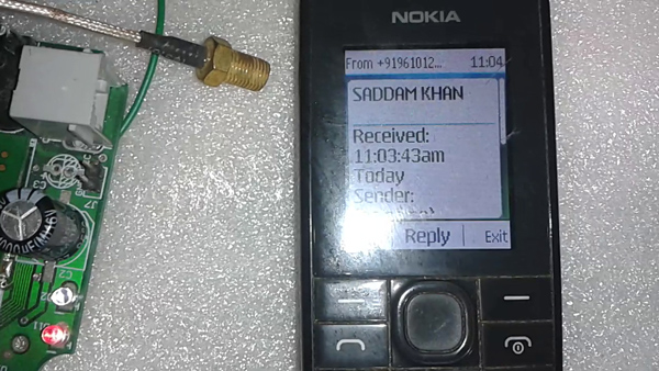
Fig. 4: Image of a mobile phone receiving SMS sent through the SMS Messaging System
The step by step working of this project is simple. To start working on the project you have to simple enter a message by using Keypad and then Press Send Button (*) we can enter the recipients number, and then by again pressing the Send Button, you can send the entered message with quite an ease.
Block Diagram & Circuit Description
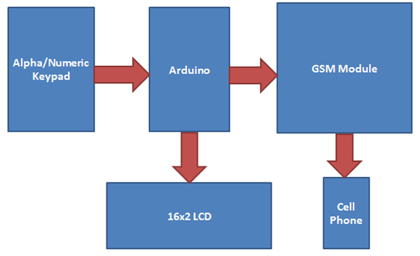
Fig. 5: Block Diagram of Arduino and GSM GPRS Module based SMS Messaging System
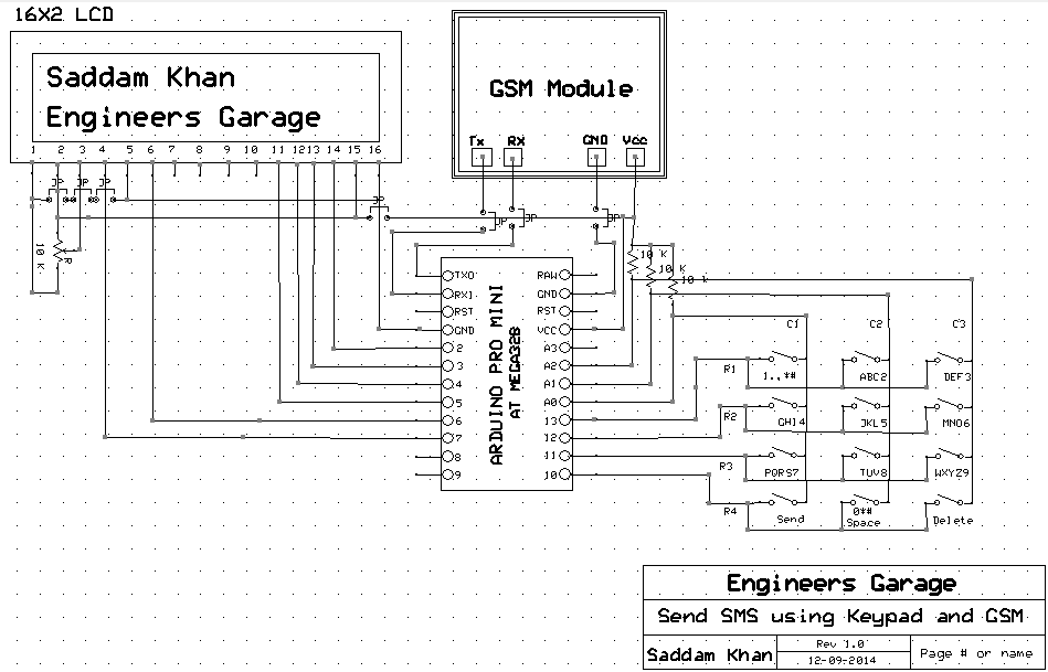
The circuit of the project is easy and simple to execute. In this a 16×2 LCD is used for displaying the Dialed Numbers which shows Button status like * for SEND and # for DELETE. A GSM Module is used for Sending Message. Arduino is used here for controlling the whole process. Also Alpha / Numeric Keypad is used in this Circuit which is used for Entering or Deleting Messages and Cell Number. Here 4×3 Numeric Keypad is used. By using this kind of Keypad you can easily enter any Alphabet (A-Z) any Number (1-9, * and #). In this project you can Delete Last Entered Digit, which means this project can also handle options for delete or for corrections at a later stage.
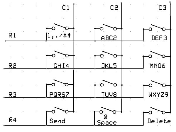
Fig. 6: Circuit Diagram of Alphanumeric Keypad
Circuit Description
GSM Module’s Rx and Txpin are directly connected with Arduino’s pinTx and Rx respectively (Ground of Arduino and GSM must be connected with each other). 16×2 LCD’s rs, en, d4, d5, d6 and d7 pins are connected with pin number 7, 6, 5, 4, 3 and 2 o Arduino respectively.
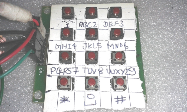
Fig. 7: Image of Alphanumeric Keypad used in SMS Messaging System
4×3 Keypad’s Row pins R1, R2, R3, R4 are directly connected with pin Number 13,12, 11, 10 of Arduino and Colum pin of Keypad C1, C2, C3 are connected with pin Number 14, 15, 16 (A0, A1, A2) of Arduino. With the Colum 10K pull up Resistor should be connected for proper keys. Please refer Circuit Diagram Tab for Circuit
Programming & Components Used
Programming
Programming part of this project is very simple as no Keypad Library is used for getting Keys. Here if statement is used for getting Key pressed.
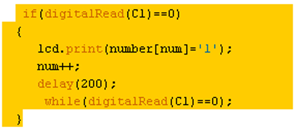
Fig. 8: Screenshot of Arduino Code used to print dialed number on Character LCD
Also the Key is adaptable to multi functioning, which means we can enter the Whole characters and Integers by using only 12 keys.
If we press key 2 (ABC2), it will show A, and if we press it again and we rewrite it, it will replace A to B and if we again press, it will show C at same place in LCD. If we wait for a while after pressing any key, cursor will show at the next position in LCD. It means now you can enter next Character or Number. This operation is likewise for rest of the Keys. To get more clarity on this watch the attached video.
Components Used
1. Arduino
2. GSM Module
3. Keypad
4. 16×2 LCD
5. Connecting Wires
6. Power Supply
Project Source Code
###
#include<LiquidCrystal.h> LiquidCrystal lcd(7, 6, 5,4, 3, 2); #define R1 13 #define R2 12 #define R3 11 #define R4 10 #define C3 16 //A2 #define C2 15 //A1 #define C1 14 //A0 int i,j,r=0,c=0,num,m; char value; int temp=0; char msg[100]; char number[10]; void setup() { Serial.begin(9600); pinMode(R1, OUTPUT); pinMode(R2, OUTPUT); pinMode(R3, OUTPUT); pinMode(R4, OUTPUT); pinMode(C1, INPUT); pinMode(C2, INPUT); pinMode(C3, INPUT); digitalWrite(R1, HIGH); digitalWrite(R2, HIGH); digitalWrite(R3, HIGH); digitalWrite(R4, HIGH); lcd.begin(16,2); lcd.setCursor(0,0); lcd.print("Sending Message "); lcd.setCursor(0,1); lcd.print("Using Keypad And"); delay(3000); lcd.setCursor(0,0); lcd.print(" GSM By Saddam "); lcd.setCursor(0,1); lcd.print("Engineers Garage"); delay(3000); lcd.clear(); } void loop() { c=0;r=0; num=0; m=0; lcd.setCursor(0,0); lcd.print("Enter New Message"); delay(2000); lcd.clear(); lcd.setCursor(0,0); temp=0; while(temp==0){Text();} while(temp==1){Text();} } void Text() { digitalWrite(R1, LOW); lcd.cursor(); /* key 1*/ if(digitalRead(C1)==0) { if(temp==1) { lcd.print(number[num]='1'); num++; delay(200); } else { lcd.noCursor(); value=49; for(i=0;i<200;i++) for(j=0;j<700;j++) { if(digitalRead(C1)==0) { lcd.setCursor(c,r); lcd.print(msg[m]=value); value--; if(value==32) value=49; while(digitalRead(C1)==0); i=0,j=0; delay(100); } } m++; } c++; if(c==16) { c=0;r=~r; } while(digitalRead(C1)==0); } /*key 2*/ if(digitalRead(C2)==0) { if(temp==1) { lcd.print(number[num]='2'); num++; delay(100); } else { lcd.noCursor(); value=65; delay(10); for(i=0;i<200;i++) for(j=0;j<700;j++) { if(digitalRead(C2)==0) { lcd.setCursor(c,r); lcd.print(msg[m]=value); value++; if(value==68) { value=50; } if(value==51) { value=65; } while(digitalRead(C2)==0); i=0,j=0; delay(100); } } m++; } c++; if(c==16) { c=0; r=~r; } while(digitalRead(C2)==0); } if(digitalRead(C3)==0) { if(temp==1) { lcd.print(number[num]='3'); num++; delay(200); } else { lcd.noCursor(); value=68; delay(10); for(i=0;i<200;i++) for(j=0;j<700;j++) { if(digitalRead(C3)==0) { lcd.setCursor(c,r); lcd.print(msg[m]=value); value++; if(value==71) value=51; if(value==52) value=68; while(digitalRead(C3)==0); i=0,j=0; delay(100); } } m++; } c++; if(c==16) { c=0;r=~r; } while(digitalRead(C3)==0); } digitalWrite(R1, HIGH); digitalWrite(R2, LOW); /* key 4 */ if(digitalRead(C1)==0) { if(temp==1) { lcd.print(number[num]='4'); num++; delay(200); } else { lcd.noCursor(); value=71; delay(10); for(i=0;i<200;i++) for(j=0;j<700;j++) { if(digitalRead(C1)==0) { lcd.setCursor(c,r); lcd.print(msg[m]=value); value++; if(value==74) value=52; if(value==53) value=71; while(digitalRead(C1)==0); i=0,j=0; delay(100); } } m++; } c++; if(c==16) { c=0;r=~r; } while(digitalRead(C1)==0); } /*key 5 */ if(digitalRead(C2)==0) { if(temp==1) { lcd.print(number[num]='5'); num++; delay(200); } else { lcd.noCursor(); value=74; delay(10); for(i=0;i<200;i++) for(j=0;j<700;j++) { if(digitalRead(C2)==0) { lcd.setCursor(c,r); lcd.print(msg[m]=value); value++; if(value==77) value=53; if(value==54) value=74; while(digitalRead(C2)==0); i=0,j=0; delay(100); } } m++; } c++; if(c==16) { c=0;r=~r; } while(digitalRead(C2)==0); } /*key 6 */ if(digitalRead(C3)==0) { if(temp==1) { lcd.print(number[num]='6'); num++; delay(200); } else { lcd.noCursor(); value=77; delay(10); for(i=0;i<200;i++) for(j=0;j<700;j++) { if(digitalRead(C3)==0) { lcd.setCursor(c,r); lcd.print(msg[m]=value); value++; if(value==80) value=54; if(value==55) value=77; while(digitalRead(C3)==0); i=0,j=0; delay(100); } } m++; } c++; if(c==16) { c=0;r=~r; } while(digitalRead(C3)==0); } /* key 7*/ digitalWrite(R2, HIGH); digitalWrite(R3, LOW); if(digitalRead(C1)==0) { if(temp==1) { lcd.print(number[num]='7'); num++; delay(200); } else { lcd.noCursor(); value=80; delay(10); for(i=0;i<200;i++) for(j=0;j<700;j++) { if(digitalRead(C1)==0) { lcd.setCursor(c,r); lcd.print(msg[m]=value); value++; if(value==84) value=55; if(value==56) value=80; while(digitalRead(C1)==0); i=0,j=0; delay(100); } } m++; } c++; if(c==16) { c=0;r=~r; } while(digitalRead(C1)==0); } /*key 8 */ if(digitalRead(C2)==0) { if(temp==1) { lcd.print(number[num]='8'); num++; delay(200); } else { lcd.noCursor(); value=84; delay(10); for(i=0;i<200;i++) for(j=0;j<700;j++) { if(digitalRead(C2)==0) { lcd.setCursor(c,r); lcd.print(msg[m]=value); value++; if(value==87) value=56; if(value==57) value=84; while(digitalRead(C2)==0); i=0,j=0; delay(100); } } m++; } c++; if(c==16) { c=0;r=~r; } while(digitalRead(C2)==0); } /* key 9 */ if(digitalRead(C3)==0) { if(temp==1) { lcd.print(number[num]='9'); num++; delay(200); } else { lcd.noCursor(); value=87; delay(10); for(i=0;i<200;i++) for(j=0;j<700;j++) { if(digitalRead(C3)==0) { lcd.setCursor(c,r); lcd.print(msg[m]=value); value++; if(value==91) value=57; if(value==58) value=87; while(digitalRead(C3)==0); i=0,j=0; delay(100); } } m++; } c++; if(c==16) { c=0;r=~r; } while(digitalRead(C3)==0); } /* key * */ digitalWrite(R3, HIGH); digitalWrite(R4, LOW); if(digitalRead(C1)==0) { if(temp==0) { lcd.clear(); lcd.setCursor(0,0); lcd.print(" Enter Mobile "); lcd.setCursor(0,1); lcd.print(" Number "); delay(2000); lcd.clear(); lcd.setCursor(0,1); lcd.print("*= send #= del"); lcd.setCursor(0,0); temp=1; c=0;r=0; while(digitalRead(C1)==0); } else { Serial.println("AT+CMGF=1"); Serial.print("AT+CMGS=""); for(int i=0;i<10;i++) Serial.print(number[i]); delay(10); Serial.println("""); Serial.print(msg); Serial.write(26); temp=2; num=0; m=0; for(int i=0;i<100;i++) msg[i]='�'; lcd.clear(); lcd.print("Message Sent "); delay(4000); while(digitalRead(C1)==0); } } /* 0 key */ if(digitalRead(C2)==0) { if(temp==1) { lcd.print(number[num]='0'); num++; delay(200); } else { lcd.noCursor(); value=32; delay(10); for(i=0;i<200;i++) for(j=0;j<700;j++) { if(digitalRead(C2)==0) { lcd.setCursor(c,r); lcd.print(value); msg[m]=value; value=value+16; if(value==49) value=32; while(digitalRead(C2)==0); i=0,j=0; delay(100); } } m++; } c++; if(c==16) { c=0;r=~r; } while(digitalRead(C2)==0); } /* # key */ if(digitalRead(C3)==0) { if(temp==1) num--; else m--; c--; lcd.setCursor(c,r); lcd.print(' '); lcd.setCursor(c,r); while(digitalRead(C3)==0); delay(100); } digitalWrite(R4, HIGH); }###
Circuit Diagrams
Project Video
Filed Under: Electronic Projects
Filed Under: Electronic Projects


Questions related to this article?
👉Ask and discuss on Electro-Tech-Online.com and EDAboard.com forums.
Tell Us What You Think!!
You must be logged in to post a comment.