Displaying potentiometer value and temperature using LM35
In my previous tutorial series on displaying sensor data (value) on OLED display, I have explained how to display values of different sensors like a potentiometer, LM35, soil moisture sensor, DHT, HC SR04, etc. on a tiny 1” OLED display. This time, I will demonstrate and explain how to display various sensor values on a multicolor TFT LCD screen.
TFT LCDs are very widely used attractive displays that can display TEXT, digits, numbers, figures, images, graphics, etc. They are available in different sizes such as:
- Small – 1.4”, 1.8”, 2.4”
- Medium – 2.8”, 3.2”, 3.5”
- Big – 5”, 7”
Most of these TFT LCDs work on SPI protocol. All these TFT LCDs can be easily interfaced with Arduino because Arduino has SPI pins (MOSI, MISO, SCK). In Arduino IDE, there is also a TFT library.
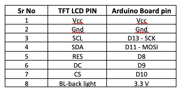
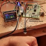
Displaying sensor data on a TFT LCD looks very attractive because it has 64K to 256K colors. Also, it is possible to show colorful TEXT or image animation on this TFT LCD using Arduino. Here, I am using a 1.8” TFT LCD with 128×160 pixels, as shown in the figure. It works on SPI protocol and has eight pins for interfacing with Arduino.
NO PIX
Let’s start with a straightforward analog sensor—potentiometer (POT). I will show you how to display the POT value on TFT LCD. The circuit diagram is followed by its connections, working, and operation.
Circuit diagram
The figure shows that the circuit consists of only three components—POT (potentiometer), Arduino NANO board, and 1.8” TFT LCD.

Circuit connections
The potentiometer has three terminals. The two end terminals are connected with +5V and GND pins of the Arduino board, as shown. The middle-slider terminal is connected with analog input pin A0. Thus, rotating POT’s analog input voltage at pin A0 varies from 0 to 5V.
The TFT LCD has a total of eight pins. It works on SPI protocol, so its pins are connected with the SPI pins of the Arduino board.
The Arduino 5V supply output directly powers the circuit. Since the Arduino is powered by the computer’s USB port (PC / laptop), there is no need for any external power supply.
Circuit operation
The POT is used to vary the analog voltage from 0 to 5V. This analog voltage is given to Arduino pin A0 as input. Arduino reads this analog voltage and converts it into a digital value between 0 to 1023. It is first converted into a string and then into an array of characters because TFT LCD can only display characters. The value is displayed as characters on TFT LCD. Arduino has a TFT library “TFT.h” that is used here along with other two libraries, “SPI.h” and “wire.h”.
The Arduino TFT library has direct functions to display TEXT, graphics, and images in various colors on the TFT LCD. Since the TFT LCD works on SPI, we need an SPI library and wire library to communicate.Below is the software program in Arduino IDE for displaying POT value on TFT LCD
Here is the snap of circuit arrangement with pot value displayed on the TFT LCD screen.
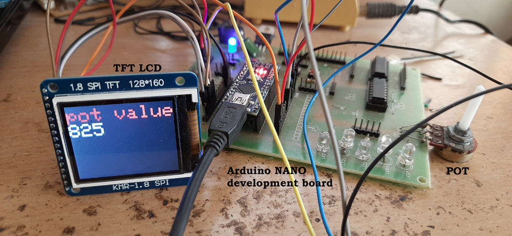
Now we can connect any analog sensor with Arduino and display its data on TFT LCD.
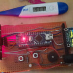
I will replace the POT with a widely-used and accurate temperature sensor, the LM35. It gives analog output voltage as ten mV/oC. Now, I will show you how to measure accurate room temperature and display it on TFT LCD. First, see the circuit diagram below.
Circuit diagram
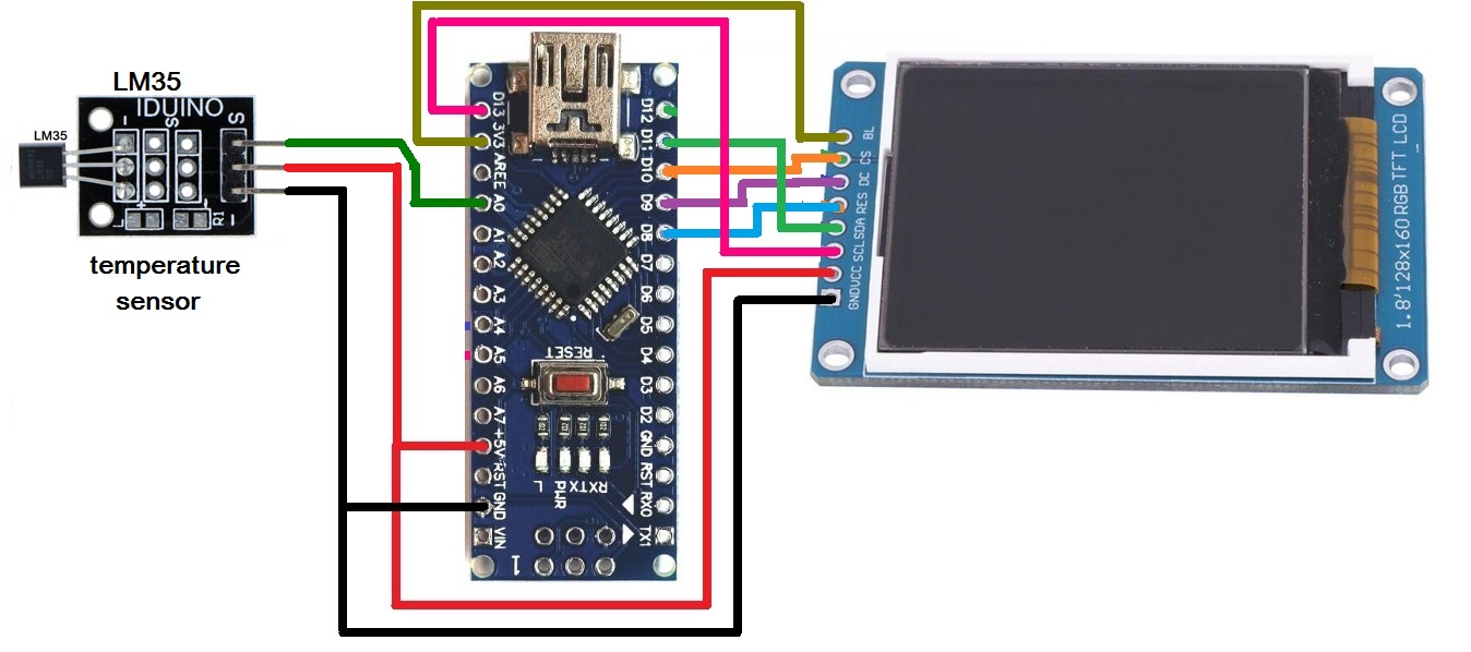 As shown in the circuit, I have replaced the LM35 sensor module in place of the POT.
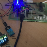
The LM35 temperature sensor module also has three pins (terminals) (1) +V (2) G(-) and (3) S (signal). +V and G(-) are connected to +5V and GND of the Arduino board. S (signal) is the sensor’s analog output and is connected to analog input pin A0 of Arduino.
Circuit operation
The LM35 sensor sense room temperature and gives analog voltage output from 0 to 1V. This analog voltage is given to Arduino pin A0 as input. Arduino reads this analog voltage and converts it into a digital value between 0 to 1023. This value is multiplied by a factor of 0.488* to get the exact room temperature value. This value is the float number. It is first converted into a string and further into an array of characters because TFT LCD can only display characters.
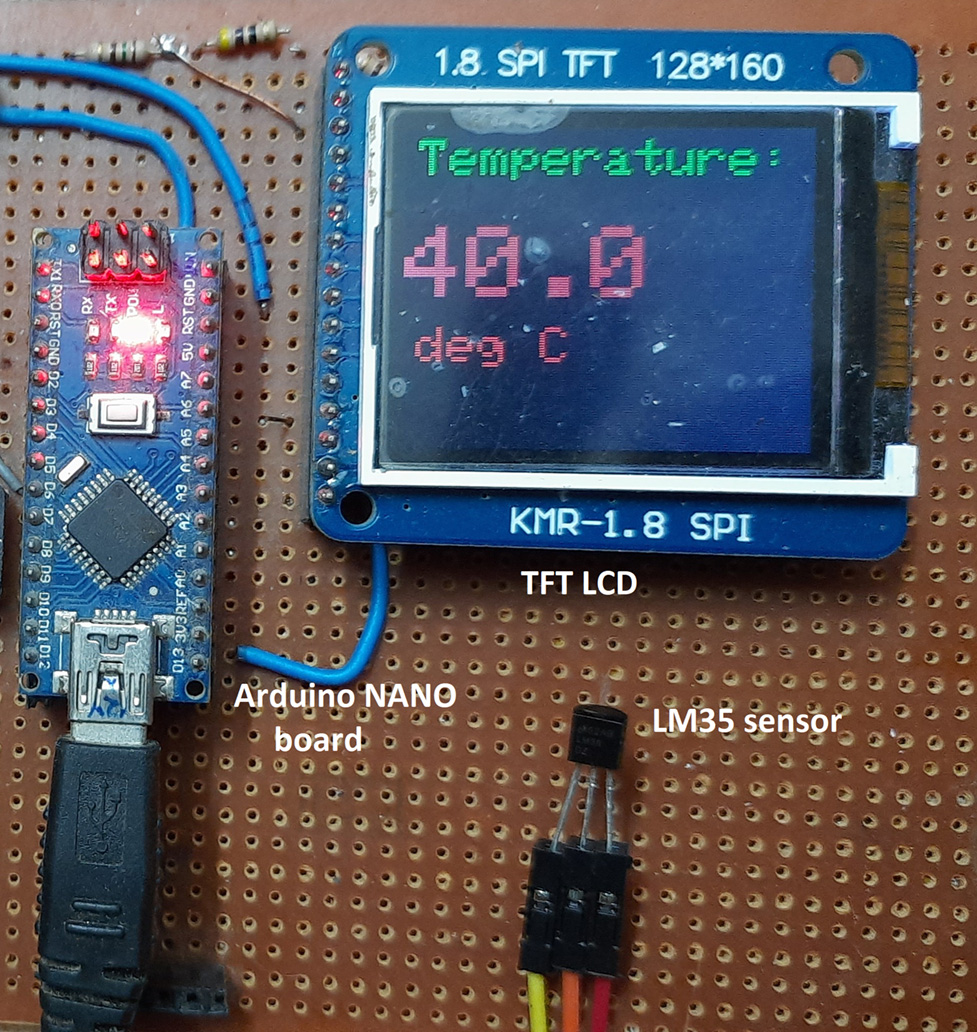
We will now display this temperature reading on TFT. It is handled again similarly by TFT library functions. Here is the program code to display room temperature on TFT LCD
Here is the snap of circuit arrangement with pot value displayed on the TFT LCD screen.
In the next article of this tutorial series, I will demonstrate how to display temperature, humidity, and soil moisture content on a TFT LCD using the DHT11 and soil moisture sensor.
*Note – detailed explanation is given in the program code
You may also like:


Filed Under: Arduino, Products, Sensors, Sensors, Tech Articles, Tutorials

Questions related to this article?
👉Ask and discuss on Electro-Tech-Online.com and EDAboard.com forums.
Tell Us What You Think!!
You must be logged in to post a comment.