Most modern instruments such as oscilloscopes, spectrum analyzers, function generators, and even some power supplies support communication with a computer through a parallel port or a serial port. This communication provides an easy and accurate way to control an experiment and collect and process data. Here we will be more focused on serial communication. In serial communication Signal can have two states 0 or 1. The signal state is determined based on voltage levels on the signal line. +5v to +15v implies state 0(low) and –5v to –15v implies signal state of 1(High).
This entire project is divided in to 2 parts, the first part demonstrates the software implementation of the serial communication between MATLAB and the PC and the second part demonstrates the hardware implementation of serial communication between the MATLAB and WSN-AK development kit (ATMEGA324PA).
Getting Started
Sending a command or data through a serial port is very similar to writing data to a file. Before tackling the problem of serial port communication. Writing data in MATLAB is accomplished using the fprintf() statement. Typing fprintf(‘PHYS352’). When you press ‘Enter’, the test string PHYS352 should appear on your screen. To direct this output to a file instead of the computer screen we need to first open a file. This is done using the fopen() statement.
For example
id=fopen(‘datafile.txt’,’w’);
will open a file called ‘datafile.txt’ that can be used for writing data (using ‘r’ in place of ‘w’ opens the file on read mode). When the fopen() statement is executed, MATLAB returns a file identifier. In this example, the value of the file identifier is captured by the variable id. Including the file identifier in the fprintf() statement, data is written to the file instead of the screen.Typing the statement
fprintf(id,’PHYS352’);
To see if the operation is successful we can examine the contents of the file datafile.txt. However, before we can do this, you will need to close the file. This is done by using
fclose(id)
Close the file and check that the text string was stored in the file successfully.
(For example, enter the command type datafile.txt) Data can be read from the file using the
fscanf()
Reopen the file, this time using ‘r’ in place of ‘w’ to indicate that you want to read from the file. Enter
data=fscanf(id,’%s’)
The argument ‘%s’ is a conversion character that indicates that we want to read a string of characters. (Examples of other conversion characters are %d for decimal, %f for fixed point, and %e for exponential notation.) The variable data should now hold the character string ‘PHYS352’. Very similar operations are performed when you want to communicate with an instrument using the serial port.
Serial IO with MATLAB (quick launch)
The following steps are required for serial data communication
Create serial port object. Use MATLAB command serial
Configure serial port object. get and set commands
Connect to the device. Fopen
Configure if required. get and set commands
Write data with fprintf command. Read data with fscanf command.
Disconnect device on transmission over. Use fclose
MATLAB Program for Serial Port Communication :
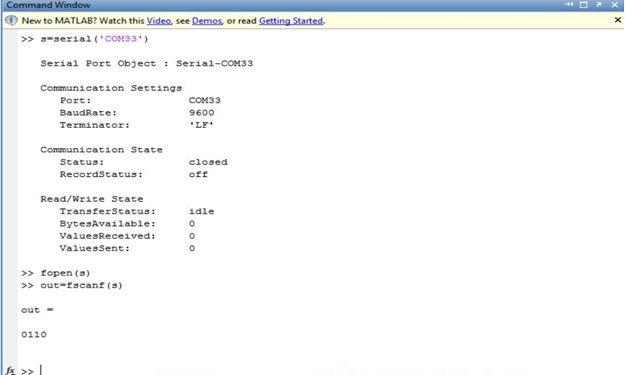
Before we can send or receive information using a serial port, we must first identify what port will be used (COM1 or COM2). This is done by using the serial command. For example,
s=serial(‘COM1’);
selects COM1 and returns an identifier which is captured by the variable ‘s’. If we enter the command without the ‘;’ and press return, the current settings of COM1 should be
displayed.
The output for a particular computer is shown below:
s=serial(‘COM1’)
Serial Port Object: Serial-COM1
Communication Settings
Port: COM1
BaudRate: 1200
Terminator: ‘CR’
Communication State
Status closed
RecordStatus: off
Read/Write State
TransferStatus: idle
BytesAvailable: 0
ValuesReceived: 0
ValuesSent: 0
It is obviously important that the serial port on the computer and the oscilloscope are configured in
exactly the same manner. You can change the serial port settings using ‘s. commands’. (Note: ‘s’ is the serial port identifier assigned when the serial command was executed.) For example, on a particular computer: s.BaudRate = 9600; changed the Baud rate from 1200 to 9600, and s.Terminator = ‘LF’; changed the line terminator from a ‘carriage return’ to a ‘line feed’. Ensure that the Baud rate on the COM1 port of your computer is 9600, and that the terminator is a ‘LF’. To see a complete list of the COM1 settings,
Type : get(s)
Although you do not need to be concerned with most of the properties (the default settings are probably fine, there are two properties of the serial port that you may need to change. One is the Timeout and the other is the Input Buffer Size.
The Timeout property tells the computer how long to wait during the data transfer before deciding that something is wrong and terminating the transfer.
Input buffer size is the size of the buffer in which received will be stored.
Resize the buffer size using:
s.InputBufferSize = 50000;
It must be noted that some properties can be set only before establishing connection
Terminator property: This property is associated with use of fprintf (for writing to serial port) fgets, fgetl & fscanf(for read operation). It can be any value from 1 to 127.
Ex: fgetl will read a set of bytes till terminator is found. fprintf will replace n with this terminator character.
The serial port on the computer side of the system should now be ready to go.
Software Implementation
SOFTWARE IMPLEMENTATION
To communicate with serial port using MATLAB. Data from a Virtual Terminal will be read and send with the help of Proteus Avr Software. Virtual Port will be set up using Virtual Serial Port 7.0 software
Required Materials
The following materials are required:
MATLAB Software
Proteus AVR Software
Virtual Serial Port Software
Procedure
Initially we will set up the virtual serial port
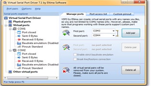
Once the virtual Port is set we can configure it by going MyComputer à Manage àDevice Manager à Ports(COM & LPT).Our next task will be to set the schematic diagram in the AVR Proteus Software
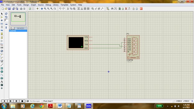
The port p1 setting could be changed by double clicking on component .Here the physical Port was set to COM1 and the physical and the virtual baud rate was set to 9600 .Once the schematic diagram shown above is simulated a virtual terminal will appear on which a sent and received could be seen.(NOTE: The sent data could be seen by ticking the echo type character on virtual terminal).
MATLAB Programming
close all; % close all figures
clear all; % clear all workspace variables
clc; % clear the command line
fclose(‘all’); % close all open files
delete(instrfindall); % Reset Com Port
BAUDRATE = 9600;
INPUTBUFFER = 512;
s=serial(‘COM1’);%s is an identifier of the serial port
set(s,’BaudRate’,BAUDRATE);%baudrate is set to 9600
set(s,’InputBufferSize’, INPUTBUFFER);%input buffer size is set to 512
set(s,’Terminator’,’CR’);%terminator is carriage return
fopen(s);%the port is opened
tx=’AMAN BAJAJ SERIAL PORT PROJECT’;fprintf(s,’%s’,tx);
The output at the virtual terminal will be shown as following:
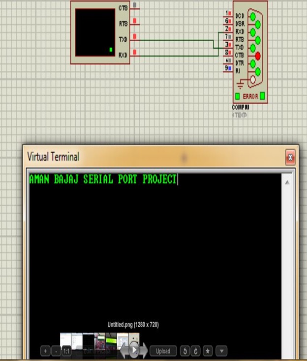
The data could also be sent to MATLAB by writing the text at the virtual terminal.
Example : By writing ‘SERIAL PORT PROJECT THROUGH MATLAB’ in terminal window we will get output as:-

Hardware Implementation
HARDWARE IMPLEMENTATION
INTRODUCTION
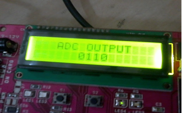
To communicate with serial port using MATLAB. Data will be sent by WSN-EK development kit by PERVCOM (if not availiable then we can use simple ATMEGA32 chip and burn the code on it). The value of the Potentiometer(present on the kit) will be send to one of the channel of the ADC (analog to digital converter) present in ATMEGA324PA and finally the obtained digital value will be send serially(USART) to MATLAB.
Required Materials
The following materials are required:
WSN-EK development kit by PERVCOM
USB (Universal Serial Bus) AVR Programmer
A computer running Windows , with a free USB port, and the following
software installed:
a mikroC PRO for AVR
b eXtreme Burner – AVR
Relevant accessories such as serial cables, power adaptors, etc
Preliminary knowledge of embedded programming environment with C will be helpful.
Procedure
We will start the project by writing the program in mikroC pro . As we know the potentiometer will provide us with analog value which should be converted to digital value. The digital value obtained will be transmitted synchronously.
The output from the above program will be a plot, which will change as we will rotate the potentiometer knob present on the WSN-AK development kit.
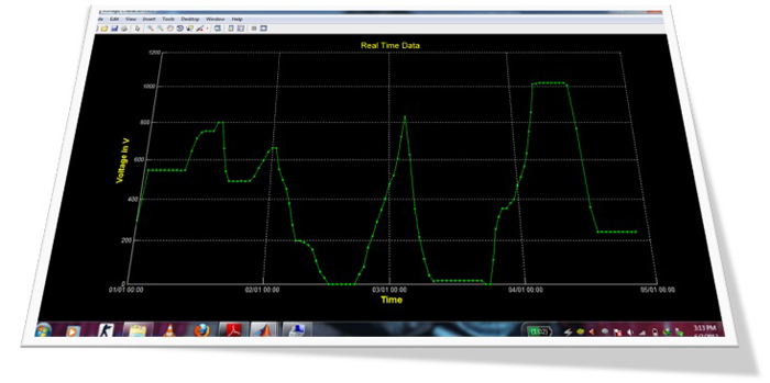
Here the loop is set to run for 120 times thus we got the plot for 120 different adc values.
Project Source Code
Project Source Code
###
MIKROC PROGRAM :-===========================================================#include "serialmatlab.h"unsigned char digit0,digit1,digit2,digit3,serial_data;sbit LCD_RS at PORTB2_bit; //The sbit type defines a bit within a specialsbit LCD_EN at PORTB3_bit; //function register (SFR).sbit LCD_D4 at PORTD4_bit;sbit LCD_D5 at PORTD5_bit;sbit LCD_D6 at PORTD6_bit;sbit LCD_D7 at PORTD7_bit;sbit LCD_RS_Direction at DDB2_bit;sbit LCD_EN_Direction at DDB3_bit;sbit LCD_D4_Direction at DDD4_bit;sbit LCD_D5_Direction at DDD5_bit;sbit LCD_D6_Direction at DDD6_bit;sbit LCD_D7_Direction at DDD7_bit;void main(void){unsigned int adcount;unsigned char txtm[15];Initialize_switch_led_relay();Lcd_Init();LCD_Cmd(_LCD_CURSOR_OFF); // send command to LCD (cursor off)LCD_Cmd(_LCD_CLEAR); // send command to LCD (clear LCD)Delay_ms(20);Initialize_uart();LCD_Out(1,1," WELCOME TO ");LCD_Out(2,1," WEK DEMO ");Delay_ms(2000);LCD_Cmd(_LCD_CLEAR);Delay_ms(10);Initialize_adc();while(1) /* Infinite loop where program execution repeats */{adcount = Read_adc(5);digit0=adcount%10;adcount=adcount/10;digit1=adcount%10;adcount=adcount/10;digit2=adcount%10;digit3=adcount/10;txtm[0]=0x30+digit3;txtm[1]=0x30+digit2;txtm[2]=0x30+digit1;txtm[3]=0x30+digit0;txtm[4]=0;LCD_Out(1,1," ADC OUTPUT ");LCD_Out(2,7,txtm);Delay_ms(700);UART_transmit_pc_string(txtm);}}void Initialize_switch_led_relay(void){LED1_dir_output;LED2_dir_output;Relay_dir_output;S1_dir_input;S2_dir_input;S1_pullup_on;S2_pullup_on;LED1_off;LED2_off;Relay_off;}void Initialize_adc(void){ADMUX=ADC_VREF_TYPE & 0xff; // ADC reference voltage is set to 2.56VADCSRA=0x87; // Clock is devided by 128}unsigned int Read_adc(unsigned char channel){unsigned char Low_byte,High_byte;ADMUX=channel | (ADC_VREF_TYPE & 0xff);Delay_ms(10); // Delay needed for the stabilization of the ADC input voltageADCSRA|=0x40; // Start the AD conversionwhile ((ADCSRA & 0x10)==0); // Wait for the AD conversion to completeLow_byte=ADCL;High_byte=ADCH;// Read lower and higher bytes of converted datareturn(High_byte*255+Low_byte); // return result in 16 bit interger format}void Initialize_uart(void){UBRR0H=0;UBRR0L=51; /* Value of UBRRL is set to 51 for 9600 baud rate */UCSR0B.F4=1; /* Bit 4 of RXEN is set to enable receiver module */UCSR0B.F3=1; /* Bit 3 of TXEN is set to enable transmitter module */}void UART_transmit_pc(unsigned char tdata){while (!( UCSR0A & (1<<UDRE0))); /* Wait for empty transmit buffer */UDR0 = tdata; /* Put data into buffer, sends the data */}void UART_transmit_pc_string(unsigned char* str){unsigned char i;i=0;while(str[i] != 0){UART_transmit_pc(str[i]);i++;Delay_ms(1);}UART_transmit_pc('n'); /*the c program is sending LINE FEED terminator}______________________________________________________________________________In the program it could be clearly seen that the analog value is converted to digital and is sent serially to pc. Now the program includes a header file named ‘MATLABSERIAL.h’ which is as follows:=====================================================================#define LED1_dir_output DDRC.DDC4=1/* LED1 is connected to bit4 of PORTC and the pin direction is definedas ouptput */#define LED2_dir_output DDRC.DDC5=1/* LED2 is connected to bit5 of PORTC and the pin direction is definedas ouptput */#define LED1_on PORTC.PORTC4=1/* LED1 may be switched ON by sending '1' to the associated pin */#define LED2_on PORTC.PORTC5=1/* LED2 may be switched ON by sending '1' to the associated pin */#define LED1_off PORTC.PORTC4=0/* LED1 may be switched OFF by sending '0' to the associated pin */#define LED2_off PORTC.PORTC5=0/* LED2 may be switched OFF by sending '0' to the associated pin */#define Relay_dir_output DDRC.DDC3=1/* Relay driver circuit is connected to bit3 of PORTC and the pin isdefined as ouptput pin */#define Relay_on PORTC.PORTC3=1/* Relay may be switched ON by sending '1' to the associated pin */#define Relay_off PORTC.PORTC3=0/* Relay may be switched OFF by sending '0' to the associated pin */#define S1_dir_input DDRC.DDC1=0/* Switch S1 is connected with bit 1 of PORTC and the pin directiondefined as input */#define S2_dir_input DDRC.DDC0=0/* Switch S2 is connected with bit 0 of PORTC and the pin directiondefined as input */#define S1_pullup_on PORTC.PORTC1=1/* The internal pull up resistance with S1 pin is turned ON *//* Pull-up resistors are used in electronic logic circuits to ensurethat inputs to logic systems settle *//* are maintained at expected logic levels if external devices aredisconnected or high-impedance */#define S2_pullup_on PORTC.PORTC0=1/* The internal pull up resistance with S2 pin is turned ON *//* Pull-up resistors are used in electronic logic circuits to ensurethat inputs to logic systems settle *//* at expected logic levels if external devices are disconnected orhigh-impedance */#define S1 PINC.PINC1 /* Read Status of S1 pin */#define S2 PINC.PINC0 /* Read Status of S2 pin */#define S1_pressed S1==0 /* Checking whether S1 is pressed. If S1 is pressedthe associated pin is pulled down to '0' state */#define S1_unpressed S1==1/* Checking whether S1 is unpressed. If S1 is unpressed the associatedpin is pulled up to '1' state */#define S2_pressed S2==0/* Checking whether S1 is pressed. When S2 is pressed the associatedpin is pulled down to '0' state */#define S2_unpressed S2==0/* Checking whether S1 is pressed. When S2 is unpressed the associatedpin is pulled up to '1' state */void Initialize_switch_led_relay(void);/* This function configure switches, LEDs and relay pin directions *//* and other required configuration */void Initialize_uart(void); /* This initializes UART module of ATMEGA324PA */unsigned char UART_receive_pc(void);/* This function is responsible for receiving one byte data from PC */void UART_transmit_pc_string(unsigned char*);/* This function is responsible for transmitting a data string to PC */void UART_transmit_pc(unsigned char);/* This function is responsible for transmitting one byte data to PC */#define ADC_VREF_TYPE 0xC0 //Internal 2.56V Voltage Reference with external//capacitor at AREF pin */#define Enter_4bit_mode {Lcd_command(0x33);Lcd_command(0x32);}/* To enter into 4 bit mode of operation *//* these two commands must be sent sequentially */void Initialize_adc(void); /* This function initializes ADC module */unsigned int Read_adc(unsigned char);/* This function reads the digital value of the analog voltage *//*present at a particular channel passed as parameter and returns the*//* converted 10 bit digital value */=====================================================================( NOTE : The above program is written for mikroC software which has an inbuilt library functions, thus the LCD library function should be included from the Library Manager. )The hex file of mikroc program will now be burned into the the Atmega324PA microcontroller present on the WSN-EK development kit%%real time data plot from a serial port% This matlab script is for ploting a graph by accessing serial port data in% real time. Change the com values and all variable values accroding to% your requirements. Dont forget to add terminator in to your serial device program after every new data% This script can be modified to be used on any platform by changing the% serialPort variable.% Author: AMAN BAJAJ%%Clear all variablesclear all;%%Variables (Edit yourself)SerialPort='com33'; %serial portMaxDeviation = 3;%Maximum Allowable Change from one value to nextTimeInterval=0.2;%time interval between each input.loop=120;%count values%%Set up the serial port objects = serial(SerialPort)fopen(s);time =now;voltage = 0;%% Set up the figurefigureHandle = figure('NumberTitle','off',...'Name','Voltage Characteristics',...'Color',[0 0 0],'Visible','off');% Set axesaxesHandle = axes('Parent',figureHandle,...'YGrid','on',...'YColor',[0.9725 0.9725 0.9725],...'XGrid','on',...'XColor',[0.9725 0.9725 0.9725],...'Color',[0 0 0]);hold on;plotHandle = plot(axesHandle,time,voltage,'Marker','.','LineWidth',1,'Color',[0 1 0]);xlim(axesHandle,[min(time) max(time+0.001)]);% Create xlabelxlabel('Time','FontWeight','bold','FontSize',14,'Color',[1 1 0]);% Create ylabelylabel('Voltage in V','FontWeight','bold','FontSize',14,'Color',[1 1 0]);% Create titletitle('Real Time Data','FontSize',15,'Color',[1 1 0]);%% Initializing variablesvoltage(1)=0;time(1)=0;count = 2;k=1;while ~isequal(count,loop)%%Recreating Serial port before timeoutk=k+1;if k==25fclose(s);delete(s);clear s;s = serial('com33');fopen(s)k=0;end%%Serial data accessingvoltage(count) = fscanf(s,'%f');%%For reducing Error Use your own costant%voltage(1)=0;%if (voltage(count)-voltage(count-1)>MaxDeviation)% voltage(count)=voltage(count-1);%endtime(count) = count;set(plotHandle,'YData',voltage,'XData',time);set(figureHandle,'Visible','on');datetick('x','mm/DD HH:MM');pause(TimeInterval);count = count +1;end%% Clean up the serial portfclose(s);delete(s);
clear s;
###
Filed Under: Electronic Projects

Questions related to this article?
👉Ask and discuss on EDAboard.com and Electro-Tech-Online.com forums.
Tell Us What You Think!!
You must be logged in to post a comment.