Basic and popular battery monitoring technique – Voltage Divider CircuitBasic and the most popular individual battery monitoring technique using microcontrollers in practice is voltage divider circuit. In voltage divider circuit two resistors are connected in series and source (battery) voltage is applied across its ends. Voltage is divided against the two resistors according to the resistor ohmic values.
|
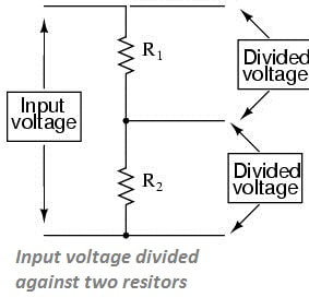
Why voltage divider?
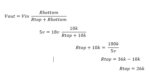
Now lets calculate the values for Rtop and Rbottom. Here we need some important considerations to be taken seriously.
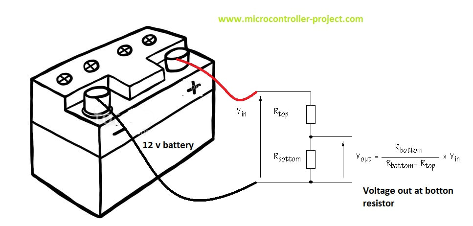
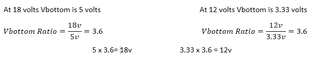
- Low ohm resistors can sunk much current and wires could be heated instantly. Consequently wires can melt down in seconds. So always use sufficient amount of resistors for bigger ampere hour batteries. I selected one resistor Rbottom to be 10k ohm.
- During charging battery voltage can increase to 18 volts. For example150 watt solar panel outputs 17 volts at 6 amperes during full sun, output voltage can even reach above 18 volts. Solar charge controller also output voltage approximately equal to 15 volts to charge the batteries.
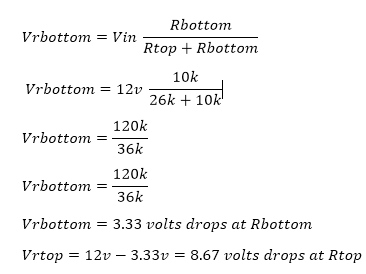
Calculating resistance values
Batteries connected in series
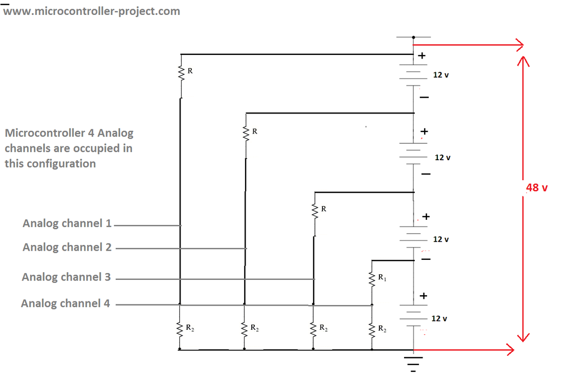
In the above circuit four voltage divider circuits are used to measure voltage across each battery. The technique is to measure the voltage across high potential battery first, than against the lower ones and negating the subsequent batteries voltage from the one at higher potential. For example for the above circuit the measured voltage across battery-1 is 48v and battery-2 is 36v. Negating 48v-36v=12v gives us battery-1 voltage. Similarly if battery-3 is at 23v. Than 36v-23v gives 13v. So battery-2 is supplying 13 volts in series string array. Other batteries voltages can be calculated with same method.
In the above scenario for each battery their must be a dedicated analog channel. For higher string of batteries more analog channels are required and microcontrollers usually have 8 analog channels at max. So this method is feasible only when batteries in series combination are not greater than 4.
Note: For the above circuit the resistors values should be selected using the same formula given above.
A demo project using the above technique is made with arduino uno. Project contains free source code and circuit diagram. If you are interested take the tutorial. The link is below.
Opto-isolators or Optocouplers
You can find many linear optocouplers with different ratings from Texas instruments and other vendors online. At the end the circuit will be hard to design and configure. A typical example is below. I hope no one has time to spend on it 😀

Relays in battery monitoring
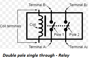 Double pole single through relay
double pole single through relay is best choice here. A double pole single through relay has a single coil and double channels. When coil is energized two contacts are instantly made. Since two contacts are made. Battery both positive and negative terminals can be connected to this relay for input. A typical foot print of DPST relay is shown on the right hand side. Normally both the terminals are open and upon coil activation both the poles moves and completes the circuit line through which electric power can flow now.
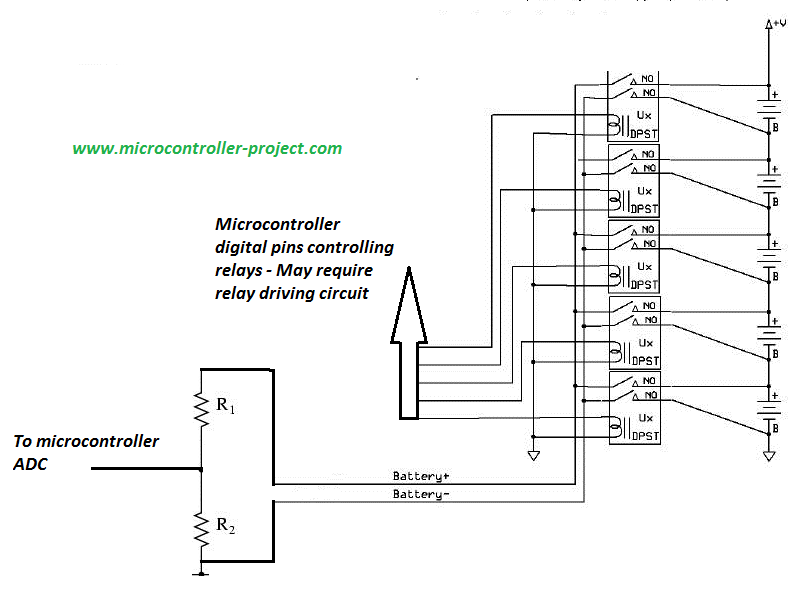
The circuit seems to be pretty simple in diagram but their are some serious pros and cons.
Pros
- Only one analog channel of microcontroller is required to measure multiple batteries.
Cons
- Digital pins of microcontrollers are required to activate the relay coils and for individual battery an individual pin is required. Digital pins can be reduced by using multiplexers.
- Each relay must be properly switched on and off one by one. If the two relays accidentally switched on at the same time their will be a huge blast due to short circuit of batteries.(It happen with me) .
- Relay on off increases response time of voltage monitoring.
- Relay driving circuit is required.
I used arduino mega to monitor a cluster of 32 batteries with the same relay method. I used ULN2003 relay driver to drive the relay coils. UL2003 input is connected to multiplexer output. 4 to 16 multiplexer is used to drive 2 ULN2003 drivers. First i short circuited the 2 batteries and it cost me much at the end i finally fixed the code and inserted some delays which increased the hardware efficiency.
I made a simple diy project with the same above logic. Arduino relay is used in the project. Click the below button to take the tutorial.
Analog Multiplexers
Batteries connected in parallel
If you are a DIY circuit maker or an electronics getting started enthusiastic or if you are a electronic major student the below mentioned project is for you. Its monitoring your car battery voltage, engine temperature and automatically switching head lights on off. Tutorial link is below.
You may also like:


Filed Under: Arduino, Arduino., ARM, ARM., AVR, AVR., Batteries, ESP8266., PIC Microcontroller., Products, STM32., Tech Articles

Questions related to this article?
👉Ask and discuss on EDAboard.com and Electro-Tech-Online.com forums.
Tell Us What You Think!!
You must be logged in to post a comment.