Beaglebone Black Servo Motor Control
This tutorial explains about the fundamental use of PWM where servo motor is controlled by potentiometer. It is a DC motor which operates on electrical pulse. You can directly interface servo motor with Beaglebone black without any driver IC. For this you have to write a program in python script with adafruit PWM and ADC library.
Required Tools:
- Beaglebone Black
- Servo motor ( Micro servo 9g)
- Potentiometer ( 5k Ω )
- 1 k Ω Resistor
- Breadboard
- Female to Female connectors
Setup of Software environment
Install the latest python version in BBB as explained in tutorial How to make first python program with Beaglebone Black. Install the adafruit python-GPIO library named adafruit_BBIO.
Working
It is a simple learning tutorial in which I have interfaced servo motor and potentiometer with Beaglebone black. When script is being executed, it enters into a continuous loop. Servo motor’s position varies according to the value of potentiometer. If you vary the value of potentiometer, servo motor’s rotational angle also changes. When the entered angle value reaches the threshold value of servo motor, exit form continuous loop and stop the program. Press ctrl+C to stop the execution of program form SSH command terminal.
Description
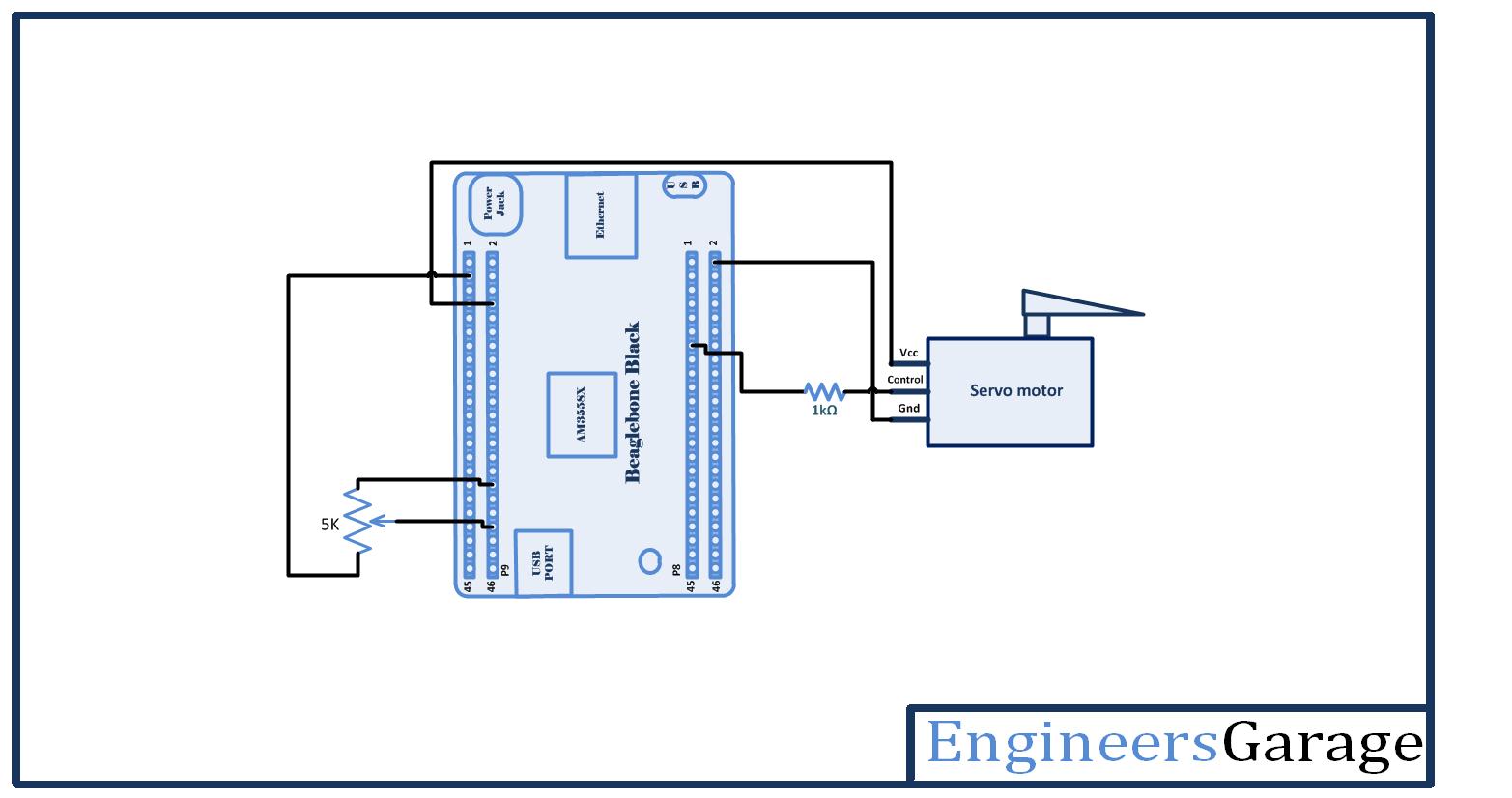
Let’s first prepare the circuit connection. Take a breadboard and provide VCC and ground from BBB to breadboard line. Servo motor requires 4.8 V while Potentiometer needs only 3.3 V. BBB has 5 V on chip system and 3.3 V on pin header which allows you to draw both supplies from Beaglebone Black. System 5 V is drawn for Servo motor and 3.3V is drawn for potentiometer. On one side of breadboard, Connect Supply 3.3 V from pin number 3rd of header P9 and ground from pin number 2nd of header P8. Another side of breadboard connects supply system 5 V from pin number 8th of header P9 and makes ground common with pin number 2nd of header P8.
Potentiometer has three terminals. The middle one is output terminal and is connected with ADC pin (40th pin of header P9) of Beaglebone black. Output of potentiometer is analog value that’s why it’s connected with ADC pin. Any left or right pin of potentiometer is connected with 3.3 V and remaining pins are connected with ADC ground pin (34th pin of header P9).
Servo motor has also three terminals:
Orange wire – Pulse input
Red wire – Vcc
Brown wire – Ground
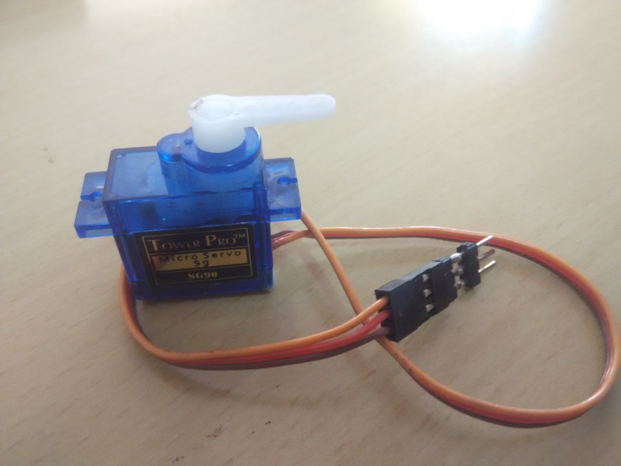
Servo motor is rotary actuator which controls the linear or angular position of motor. It is controlled by electrical pulse with various width or Pulse Width Modulation. BBB has on chip PWM pin. Servo motor is interfaced with PWM pin (13th pin of header P8) of BBB. I have interfaced 1k ohm resistor between the two so as to protect it from unnecessary damage.
You may also like:
Project Source Code
Project Source Code
###
import Adafruit_BBIO.PWM as PWMimport Adafruit_BBIO.ADC as ADCservo_pin = "P8_13"sensor_pin = 'P9_40'ADC.setup()duty_min = 85duty_max = 95duty_span = duty_max - duty_minPWM.start(servo_pin, (100-duty_min), 60.0)while True:reading = ADC.read(sensor_pin)angle = reading * 1800if angle > 270:PWM.stop(servo_pin)PWM.cleanup()breakanglefl = float(angle)duty = 100 - ((anglefl / 180) * duty_span + duty_min)PWM.set_duty_cycle(servo_pin, duty)###
Circuit Diagrams
Project Video
Filed Under: BeagleBone., Electronic Projects
Filed Under: BeagleBone., Electronic Projects




Questions related to this article?
👉Ask and discuss on Electro-Tech-Online.com and EDAboard.com forums.
Tell Us What You Think!!
You must be logged in to post a comment.