Engineers Garage

  • Electronic Projects & Tutorials
    • Electronic Projects
      • Arduino Projects
      • AVR
      • Raspberry pi
      • ESP8266
      • BeagleBone
      • 8051 Microcontroller
      • ARM
      • PIC Microcontroller
      • STM32
    • Tutorials
      • Audio Electronics
      • Battery Management
      • Brainwave
      • Electric Vehicles
      • EMI/EMC/RFI
      • Hardware Filters
      • IoT tutorials
      • Power Tutorials
      • Python
      • Sensors
      • USB
      • VHDL
    • Circuit Design
    • Project Videos
    • Components
  • Articles
    • Tech Articles
    • Insight
    • Invention Stories
    • How to
    • What Is
  • News
    • Electronic Product News
    • Business News
    • Company/Start-up News
    • DIY Reviews
    • Guest Post
  • Forums
    • EDABoard.com
    • Electro-Tech-Online
    • EG Forum Archive
  • DigiKey Store
    • Cables, Wires
    • Connectors, Interconnect
    • Discrete
    • Electromechanical
    • Embedded Computers
    • Enclosures, Hardware, Office
    • Integrated Circuits (ICs)
    • Isolators
    • LED/Optoelectronics
    • Passive
    • Power, Circuit Protection
    • Programmers
    • RF, Wireless
    • Semiconductors
    • Sensors, Transducers
    • Test Products
    • Tools
  • Learn
    • eBooks/Tech Tips
    • Design Guides
    • Learning Center
    • Tech Toolboxes
    • Webinars & Digital Events
  • Resources
    • Digital Issues
    • EE Training Days
    • LEAP Awards
    • Podcasts
    • Webinars / Digital Events
    • White Papers
    • Engineering Diversity & Inclusion
    • DesignFast
  • Guest Post Guidelines
  • Advertise
  • Subscribe

Short Circuit Detector

By Dimpal Kumar Kalita April 17, 2012

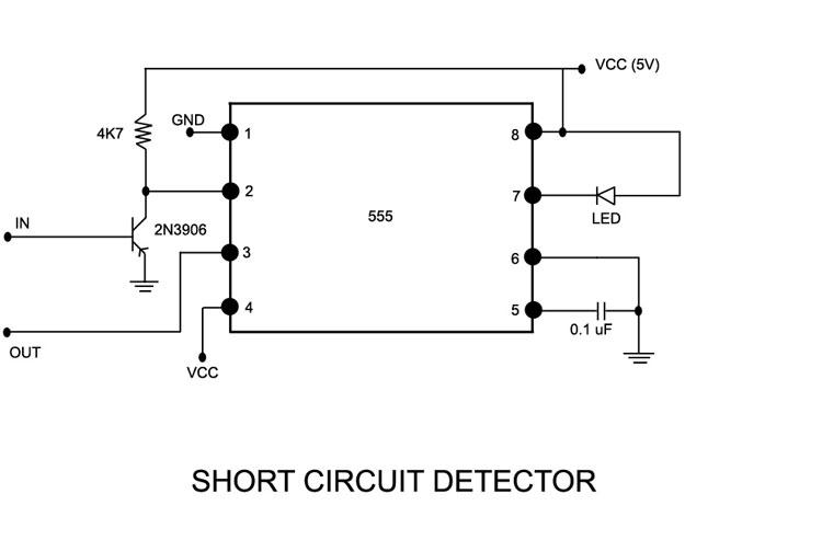
The short circuit detector described here can be used to detect short circuit condition on a LOAD operating at a maximum voltage of 12V. It is applicable to any portable devices working below 12V. The circuit employs a PNP transistor and a 555 Timer. 

COMPONENTS:
1.      555 Timer
2.      PNP Transistor (2N3906)
3.      Relay
PNP Transistor:
The PNP transistor has three working regions in its characteristic graph.
1. Cut Off region
2. Linear region
3. Saturation region 
To make the transistor work, we need to use any of these three regions. The transistor can be made to work as an amplifier or as a switch. Here in this project the intended purpose is a SWITCH. So I have used the Cutoff region and Saturation region of the transistor to make the transistor behave as a SWITCH. And if we need the transistor as an amplifier, we need to configure it in the linear region.
 
Now, a PNP transistor is activated (goes to the Saturation region) when the base-emitter voltage is less than 0.7 V for Silicon transistor and 0.3 V for Germanium transistor. Let us take the 0.7 V into account as it is the greater of the two. So if we supply less than 0.7 V to the base of the transistor, the emitter and collector of the transistor gets connected internally and if we supply greater than 0.7 V, the two terminals gets disconnected and by the time the transistor goes to Cut Off region. Thats all about the transistor.
 
Let us discuss about the 555 Timer.
The 555 Timer has basically two modes of operation.
1. Astable Mode
2. Monostable Mode
 
In the Astable mode of operation, the output of the 555 Timer changes state of its own (low and high repeatedly). The frequency depends on the external components connected to it. In this mode there is no fixed state.
 
In the monostable mode, there is one fixed (stable) state and one quasi stable which is not fixed. In the monostable mode of operation, the output of the 555 Timer generally remains low and this is known as the stable state. When it is triggered by a triggering voltage, the output goes high for a pre defined amount of time and this is known as the quasi stable state. The output then again returns to the stable or low state automatically.
 

Block Diagram of 555 Timer

 
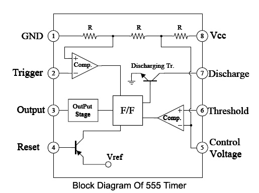
555 Timer circuits are generally designed using any one of the above mentioned modes. But this project has been designed without using any of the modes.
 
The third component used in this circuit is the Relay switch. It has been used here to cut the incoming voltage to the connected LOAD when short circuit occurs. A relay has two types of connection- One is NOMALLY CLOSED and the other is NORMALLY OPEN. While connecting a relay switch, things to remember is whether the circuit has been designed for NORMALLY CLOSED or NORMALLY OPEN and accordingly the connection is to be done to the relay.
 
This project has been designed for NORMALLY CLOSED (NC) operation of the relay and the relay SHOULD be connected to the NC terminal.
 

Operation

 
OPERATION:
To define a short circuit condition we can say that it is a condition of electrical connection across a LOAD where the positive and negative terminals of the power supply is connected directly to each other without any electrical or electronic components between them. In such condition, the current flowing through the circuit becomes maximum and the voltage across the LOAD becomes minimum. The circuit described here uses this phenomenon to detect short circuit condition.
Short Circuit Detection
The circuits are generally designed to automatically cut the supply voltage to the LOAD to avoid further damage of the circuit during the condition of short circuit. The circuit designed here can detect the short circuit condition and also can cut the supply voltage to the LOAD automatically. The short circuit condition means both the positive and negative of the supply voltage is connected directly without any resistance, inductance or capacitance between them somewhere inside the circuit.
 
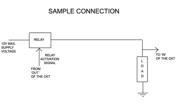
So as shown in the SAMPLE CONNECTION, the input to the transistor is taken from the positive terminal of the LOAD. So as I previously said if the transistor gets more than 0.7V in its base, it will not be activated. Now if the transistor is not activated, the emitter and collector terminal is not connected internally and the trigger terminal of the 555 Timer is connected to VCC not to ground and so the 555 Timer is not triggered and consequently the output of the 555 Timer is LOW and so the relay is not activated and thus the LOAD will continue to draw power from the power supply.
 
Now suppose a short circuit occurs due to any manual or automatic operation inside the LOAD. In this condition, current will be maximum through the LOAD and the voltage (potential difference) will be almost zero (which is less than 0.7V). This voltage will activate the transistor which in turn will connect the trigger terminal of the 555 Timer to the ground triggering the 555 Timer. Consequently the output of the 555 Timer will go high and the LED connected to PIN NO 7 of the 555 Timer will glow. Meantime, the Relay switch will be activated and will cut the power to the LOAD and thus the LOAD is SAVED for permanent damage. 


Project Source Code


Circuit Diagrams

Short-Circuit-Detector


Filed Under: 555 Timers, Electronic Projects
Tagged With: 555 timer circuit, relay, short circuit, transistor
 

Next Article

← Previous Article
Next Article →

Questions related to this article?
👉Ask and discuss on EDAboard.com and Electro-Tech-Online.com forums.


Tell Us What You Think!! Cancel reply

You must be logged in to post a comment.

EE TECH TOOLBOX

“ee
Tech Toolbox: Internet of Things
Explore practical strategies for minimizing attack surfaces, managing memory efficiently, and securing firmware. Download now to ensure your IoT implementations remain secure, efficient, and future-ready.

EE Learning Center

EE Learning Center
“engineers
EXPAND YOUR KNOWLEDGE AND STAY CONNECTED
Get the latest info on technologies, tools and strategies for EE professionals.

HAVE A QUESTION?

Have a technical question about an article or other engineering questions? Check out our engineering forums EDABoard.com and Electro-Tech-Online.com where you can get those questions asked and answered by your peers!


RSS EDABOARD.com Discussions

  • Voltage mode pushpull is a nonsense SMPS?
  • Will this TL084C based current clamp circuit work?
  • How to determine the maximum PAD frequency ?
  • Xiaomi Mijia 1C Robot problem of going backwards while working
  • Reducing "shoot-through" in offline Full Bridge SMPS?

RSS Electro-Tech-Online.com Discussions

  • Siemens large industrial PLC parts
  • Parts required for a personal project
  • Cant log in to Easy PC forum
  • Failure of polypropylene motor-run capacitors
  • Wideband matching an electrically short bowtie antenna; 50 ohm, 434 MHz

Featured – RPi Python Programming (27 Part)

  • RPi Python Programming 21: The SIM900A AT commands
  • RPi Python Programming 22: Calls & SMS using a SIM900A GSM-GPRS modem
  • RPi Python Programming 23: Interfacing a NEO-6MV2 GPS module with Raspberry Pi
  • RPi Python Programming 24: I2C explained
  • RPi Python Programming 25 – Synchronous serial communication in Raspberry Pi using I2C protocol
  • RPi Python Programming 26 – Interfacing ADXL345 accelerometer sensor with Raspberry Pi

Recent Articles

  • AC-DC power supply extends voltage range to 800 V DC
  • Infineon’s inductive sensor integrates coil system driver, signal conditioning circuits and DSP
  • Arm Cortex-M23 MCU delivers 87.5 µA/MHz active mode
  • STMicroelectronics releases automotive amplifiers with in-play open-load detection
  • Convection-cooled power controller integrates EtherCat connectivity

EE ENGINEERING TRAINING DAYS

engineering

Submit a Guest Post

submit a guest post
Engineers Garage
  • Analog IC TIps
  • Connector Tips
  • Battery Power Tips
  • DesignFast
  • EDABoard Forums
  • EE World Online
  • Electro-Tech-Online Forums
  • EV Engineering
  • Microcontroller Tips
  • Power Electronic Tips
  • Sensor Tips
  • Test and Measurement Tips
  • 5G Technology World
  • Subscribe to our newsletter
  • About Us
  • Contact Us
  • Advertise

Copyright © 2025 WTWH Media LLC. All Rights Reserved. The material on this site may not be reproduced, distributed, transmitted, cached or otherwise used, except with the prior written permission of WTWH Media
Privacy Policy

Search Engineers Garage

  • Electronic Projects & Tutorials
    • Electronic Projects
      • Arduino Projects
      • AVR
      • Raspberry pi
      • ESP8266
      • BeagleBone
      • 8051 Microcontroller
      • ARM
      • PIC Microcontroller
      • STM32
    • Tutorials
      • Audio Electronics
      • Battery Management
      • Brainwave
      • Electric Vehicles
      • EMI/EMC/RFI
      • Hardware Filters
      • IoT tutorials
      • Power Tutorials
      • Python
      • Sensors
      • USB
      • VHDL
    • Circuit Design
    • Project Videos
    • Components
  • Articles
    • Tech Articles
    • Insight
    • Invention Stories
    • How to
    • What Is
  • News
    • Electronic Product News
    • Business News
    • Company/Start-up News
    • DIY Reviews
    • Guest Post
  • Forums
    • EDABoard.com
    • Electro-Tech-Online
    • EG Forum Archive
  • DigiKey Store
    • Cables, Wires
    • Connectors, Interconnect
    • Discrete
    • Electromechanical
    • Embedded Computers
    • Enclosures, Hardware, Office
    • Integrated Circuits (ICs)
    • Isolators
    • LED/Optoelectronics
    • Passive
    • Power, Circuit Protection
    • Programmers
    • RF, Wireless
    • Semiconductors
    • Sensors, Transducers
    • Test Products
    • Tools
  • Learn
    • eBooks/Tech Tips
    • Design Guides
    • Learning Center
    • Tech Toolboxes
    • Webinars & Digital Events
  • Resources
    • Digital Issues
    • EE Training Days
    • LEAP Awards
    • Podcasts
    • Webinars / Digital Events
    • White Papers
    • Engineering Diversity & Inclusion
    • DesignFast
  • Guest Post Guidelines
  • Advertise
  • Subscribe