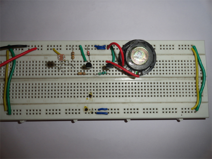
The circuit described here stops the musical sound when darkness is detected like when you put your hand above the sensor. This circuit can be used as morning alarm. Install it on your window so when the light falls on it will start giving you melodious sound to wake up. In night you can use it to switch off the light of staircase.
When you switch off the light of your room with little modification like you can connect relay at output (in place of speaker) to off the bulb. This circuit can be operated with pencil cell as it require less only 3V for its operation. It can easily be mounted because of number of components used in circuit are quite small. LDR is a device whose sensitivity depends upon the intensity of light falling on it.
The dark sensor circuit described here stops the musical sound when darkness is detected like when you put your hand above the sensor. This circuit can be used as morning alarm. Install it on your window so when the light falls on it will start giving you melodious sound to wake up. In night you can use it to switch off the light of staircase. When you switch off the light of your room with little modification like you can connect relay at output (in place of speaker) to off the bulb. This circuit can be operated with pencil cell as it require less only 3V for its operation. It can easily be mounted because of number of components used in circuit are quite small.
Description
This dark sensor circuit explains the principle of operation of LDR (light dependence resistor). LDR is a device whose sensitivity depends upon the intensity of light falling on it. The resistance of LDR decreases when intensity of light falling on it increases and vice versa (resistance increases when intensity of light falling on it decreases). In dark or in absence of light, LDR exhibits a resistance in the range of mega ohms which decreases to few hundred ohms in presence of bright light.
This phenomenon can be measure with the help of multi-meter. For measuring keep your multi-meter in ohm or resistor measurement region. When you cover the LDR its resistance will be very high and when you place it in light it decreases. We are utilizing this property of LDR to act as a sensor, since a varying voltage drop can be obtained with varying light. In this circuit amount of light is vary because of the shadow of the visitor falls on LDR. So care should be taken while mounting the LDR.
When continuous light fall on LDR its resistance is very low hence it will allow supply at pin 2 of IC1 and we get output pin 1.These weak signals then amplify by transistor and feed to speaker attached to it and we hear a melodious sound. But in darkness resistance of LDR is very high and it does not allow IC1 to conduct, therefore transistor connected at output is in cut off mode and speaker will not sound. We have connected a zener diode at pin 2 of IC1 because excess voltage more than 3.3V will harm the UM66 IC. The circuit described here is more of a sensor application with a speaker attached to it as output. However, depending upon the application, user can attach a night lamp or series of small LEDs to the circuit with the help of relay. You can also use different IC like UM3561, UM3562 etc in place UM66 if you want different sounds for this refer to datasheet of UM3561.

Fig. 1: Image Showing a Simple LDR Dark Sensor Circuit
Circuit Diagrams
Filed Under: Electronic Projects


Questions related to this article?
👉Ask and discuss on Electro-Tech-Online.com and EDAboard.com forums.
Tell Us What You Think!!
You must be logged in to post a comment.