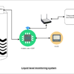
In this project, we will learn to create an automatic water pump system circuit that switches ON and OFF based on the water level in the tank.
Basic idea
The given project demonstrates a simple circuit built using digital logic gates, IC NE555, transistors, and a few additional components that sense the water level in the water tank and switch the ON/OFF water pump when the tank is empty/full. We will also illustrate what to do if there is no water in the underground water tank. A small addition to the main circuit will solve the problem. Lastly, we will present some circuits for different indications like pump ON/ pump OFF, tank empty/full, etc.
Circuit description
As shown in the figure, the circuit is built using a NAND gate, NOR gate, timer IC NE555 and a few other components like transistors, resistors, relay, etc.
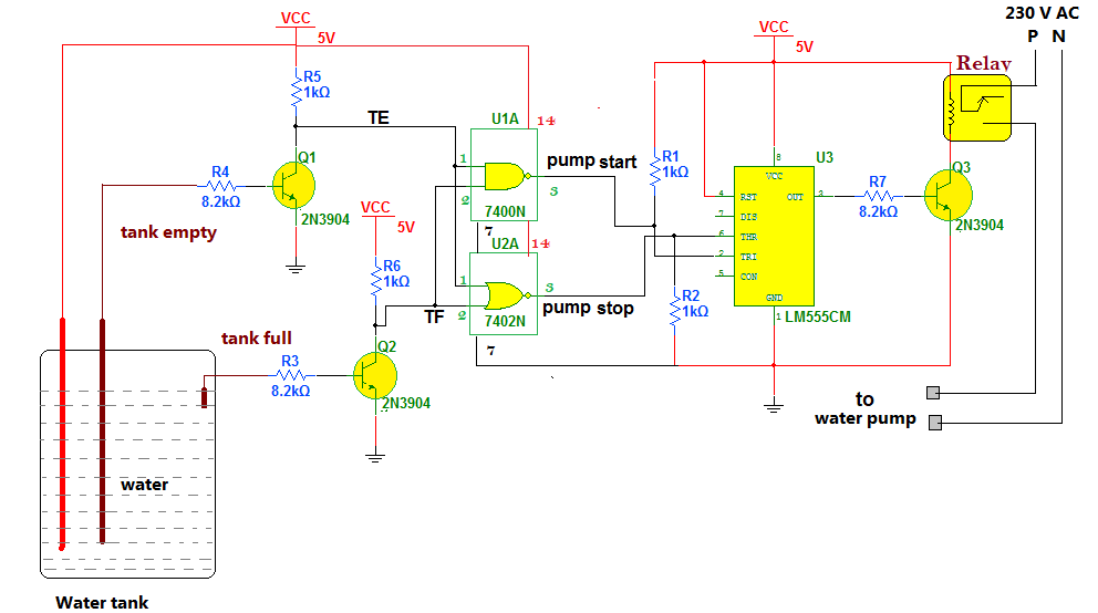
Fig.1: The complete circuit diagram of the automatic water pump system using NAND gate, NOR gate, and timer IC NE555.
- The two transistors Q1 and Q2, connected in switch mode, serve as water level sensors. Their bases are inserted into a water tank that keeps contact with water and is known as a probe.
- The +Ve supply is given to water in a tank, so if the probe is in contact with water, it also gets a +Ve supply.
- There are two sensors to sense two empty and full levels.
- The final output of the sensor is taken from a collector of the transistor. Both outputs are given as inputs to two gates NAND gate (7400) and NOR gate (7402)
- The output of the NAND gate is connected to the trigger input of IC NE555, and the output of the NOR gate is connected to the threshold input of IC NE555. IC NE555 is connected in bistable mode.
- The output of NE555 drives 1 C/O (change over) relay through one more NPN transistor Q3.
- The water pump is given 230 VAC supply through relay contact terminals C (common) and NO (normally open)
Circuit operation
- When both probes are in contact with water, they get a +Ve supply. Since transistors get +Ve input and they conduct. They give low (logic 0) outputs.
- Both outputs are given as inputs to both gates. Because both inputs are 0, the output of the NAND gate is high (logic 1 – means +Ve), and the output of the NOR gate is also high (logic 1 – means +Ve).
- Both these high outputs are given to trigger and threshold inputs to NE555, so its output remains low. The relay does not switch ON, so the water pump does not get the supply.
- When the water tank becomes empty, the probes are not in contact with water. Therefore, the transistors do not conduct and give high (logic 1) outputs.
- When the NAND gate gets both inputs as logic 1, it gives low (logic 0) output.
- Because this low output is given to trigger the input of NE555, its output goes high due to its bistable operation.
- This will switch ON the relay, and immediately water pump gets the supply and will turn ON. Thus when there is no water in a tank, the pump automatically starts.
- As the water fills up in a tank, the first lower probe comes in contact with water, giving low output. But it does not change the state of IC NE555, and the water pump remains ON.
- As the water tank fills up to full level, the upper probe also comes in contact with water; again, both transistors give low output.
- This time the NOR gate comes into action—getting both inputs low gives high output.
- As this high output is given to the threshold input to IC NE555, it immediately gives low output.
- This turns OFF the relay as well as the water pump. Thus as the water tank becomes full, the water pump automatically stops.
Adding intelligence
Usually, there are two water tanks—an overhead tank and an underground (or lower) tank. The pump supplies water from the lower tank to the overhead tank. Here, the water pump is turned ON when there is no water in the tank. If there is no water source, the pump will start, but it runs without water, which may burn or damage it.
Therefore, we need to turn off the water pump when there is no water in the lower tank. This can be done by adding a simple circuit, as shown below.
Image 2: A circuit diagram for the source/lower water system using the sensor.
The same transistor switch circuit is used as a water level sensor. Insert two sensor probes into the lower water tank—one +Ve supply and another for sensing the lower tank water level. The transistor gets +Ve input until the probe connected to the base is in touch with water, the transistor gets +Ve input. This output is combined with the pump to start the output of the previous circuit using OR gate.
When the pump starts, the output is low, and the sensor output is also low. In that case, only the trigger pin of IC NE555 gets low input from the OR gate, and the pump is switched ON through the relay. But if there is no water in the lower tank, the transistor does not conduct, and its output goes high. The output of the OR gate goes high immediately, and there is no effect on the pump start signal. The IC NE555 does not get trigger input and does not switch on the pump through the relay. As a result, the water pump does not start when there is no water in the lower tank.
Indications
To add an indication for pump ON and OFF, simply modify the IC NE555 block as shown in the figure by adding two LEDs.
- RED LED for pump OFF indication
- GREEN LED for pump ON indication
The RED LED is connected between Vcc and the output of the IC (with a current limiting resistor of 220E). When the output is low, and the pump is OFF, the RED LED is ON to indicate the pump is OFF.
The GREEN LED is connected between the IC output and ground. When the output is high and the pump is ON, the green LED is ON.
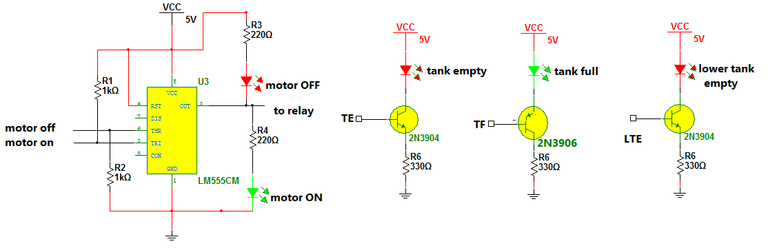
Image 3: Complete circuit diagram of upper and lower water tank system with indications.
Next, we have indications for empty, full, and lower tanks empty. There is a common type of circuit known as transistor emitter bias for all these three indications. The base inputs of transistors are connected to respective terminals TE, TF, and LTE of the above two circuits. When the tank (upper or overhead) becomes empty, the TE output goes high, so the tank empty RED LED glows to indicate the overhead tank is empty. When the overhead tank if full of water, the output is low. The PNP transistor GREEN LED glows to indicate the overhead tank is full.
The LTE output goes high when the lower tank is empty, so the empty RED LED glows to indicate the lower tank is empty.
You may also like:

Filed Under: Circuit Design, Electronic Projects

Questions related to this article?
👉Ask and discuss on Electro-Tech-Online.com and EDAboard.com forums.
Tell Us What You Think!!
You must be logged in to post a comment.