RPM counters are used to measure Speed of Motors (AC/DC) or any Rotating Object. They measures and indicates current Rotating Speed of Motor. They are very essential in applications like Speed Control of Motors and close Loop Control System. Such industrial RPM counters are very accurate made up of microcontroller or microprocessor.
The circuit presented here is simple RPM counter without any microcontroller or microprocessor. It actually measures RPS – Revolutions per Second. By just multiplying RPS – Revolutions per Second with 60 we get RPM because
Revolutions per Minute = 60 × Revolutions per Seconds
It is built using simple Components like NE555, Decade Counter CD4026, and opto-interrupt Sensor MOC7811. It counts Motor Revolutions for 1 second and displays it on 2-digit Seven Segment Display. That is the RPS. To get the RPM we have to multiply this count with 60. Not only that, the time for which it Counts Revolutions can be set to 5 second or 10 second. So for slow RPM motors we can set different time. E.g. time is set for 5 second. So revolutions are counted for 5 second. Finally
RPM = 12 × Revolution Count
Similarly if time is set for 10 second
RPM = 6 × Revolution Count
Thus for higher RPM (>1000) motors, time is set for 1 second and for lower RPM Motor time is set for 5 second or 10 second.
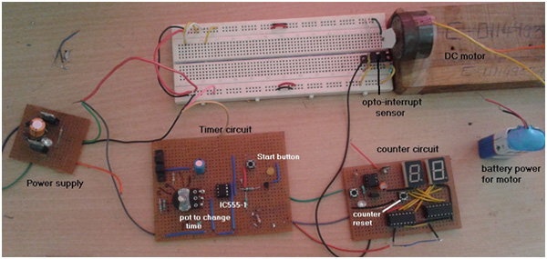
The major building blocks are opto-interrupt Sensor MOC7811, Decade Counter cum Display Driver CD4026 Common Cathode type 7 – Segment Displays and IC555.
Please Refer Circuit Tab for the Circuit Diagram
Opto Interrupt Sensor
This is the main component of entire Circuit. It converts Revolutions of Motor into Pulses. It produces 1 Pulse per one Revolution. There is an IR LED on one side and Photo Transistor on other side. IR LED is forward bias through current limiting Resistor so it is continuously ON and generates IR light. The Photo Transistor is configured in switch mode. Because IR light is continuously falling on its base it is also continuously ON and its output is low. When any objects interrupts IR Light Falling on Photo-Transistor, its output goes high for moment. Thus it generates positive pulse on every such interrupt.
Decade Counter cum Display Driver CD4026
2-digit Counter Circuit is built using two, Decade Counter cum Display Driver chips CD4026. Output of opto-interrupt Sensor is directly given as clock pulse input (pin 1) to 1st CD4026. It increment its count by 1 on every pulse input. Also it converts the count into equivalent 7-Segment Display Code (Common Cathode) so that count can be displayed. It counts from 0 to 9 and again resets to 0. When it goes from 9 to 0, it generates Output Pulse (carry out) that can be given to next decade Counter Chip. So as shown in figure the carry out (pin 5) of 1st Decade Counter is given as clock input (pin 1) to 2nd decade Counter Chip.
To reset both chips to 0 it is required to give high pulse on reset pin (no 15). So, one push button is connected to reset pins of both chips as shown to reset counter to 00. Normally both reset pins are connected to ground through 10 K resistor. Pin no 2 is clock inhibit pin. Both these pins are connected to output of Timer IC555. When these pins are low counter does not progress. Counter only increments when these pins are high.
7 – Segment Displays
The outputs of chip CD4026 are connected to a-b-c-d-e-f-g inputs of both 7 Segment Displays as shown. As the count increments it is displayed on these displays from 00 to 99 and again 00. Because they are Common Cathode type displays, their common terminals are grounded.
Timer IC555
IC 555 is configured in monostable mode. Its output pulse time is determined by RC components R1 and C1. Because R1 is 100 K pot, the maximum and minimum time period can be calculated as
Tmax = 1.1 × R1max × C1
= 1.1 × 100 × 103 × 100 × 10-6
= 11 sec
And Tmin = 1.1 × R1min × C1
= 1.1 × 100 × 100 × 10-6
= 0.011 sec
So we can set pulse time period from 1 sec to 11 sec. If we set time to 1 sec by setting pot value then the output pulse will remain high for 1 sec. That means Clock Inhibit Signal remains high for 1 sec – means counter count pulses for 1 sec only. Similarly if time set to 5 sec the counter counts for 5 seconds only. Thus we can stop counter to count further after fixed time interval. Here is image of Circuit
Hardware Setup
It is required to arrange, Motor and Sensor such a way that each revolution of motor generates one pulse as output from sensor. The arrangement is as shown in figure.
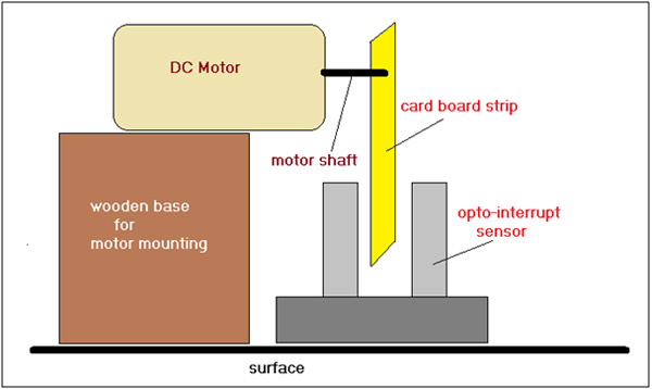
A small card board strip is attached with shaft of motor. The motor is mounted on wooden base such that the strip can easily passes through the gap of sensor as shown. Now as Motor Rotates one revolution the strip passes through sensor gap once and generates one positive pulse at the Output of Sensor. So each revolution of motor generates one positive pulse. So by counting these pulses we can count revolution per second or revolution per minute.
Circuit Operation
· When 5 V supply is given to circuit, the counter resets and displays 00 on both 7-segments. If it does not display 00, press counter reset button
· A small card-board strip is attached with shaft of motor. It is attached in such a way that when motor rotates the strip passes through the gap of MOC7811 and generates interrupt
· Give supply to motor so that it will start rotating this will start generating pulses that are given to counter
· Set pot R1 to 1 sec (or 5 sec or 10 sec)
· Now as start push button is pressed, output of IC555 goes high for 1 sec
· So counter count pulses for 1 sec given by opto-interrupt sensor.
· After 1 sec output of IC555 goes low and counter stops counting
· The last count on display shows revolution of motor per second
· Multiply it with 60 will give you RPM. E.g. if count is 33 then RPM = 33×60 = 1980 ? 2000
· Similarly if time period is set to 5 sec or 10 sec we have to multiply the count by 12 or 6
Circuit Diagrams
Project Components
Project Video
Filed Under: 555 Timers, Electronic Projects
Filed Under: 555 Timers, Electronic Projects

Questions related to this article?
👉Ask and discuss on EDAboard.com and Electro-Tech-Online.com forums.
Tell Us What You Think!!
You must be logged in to post a comment.