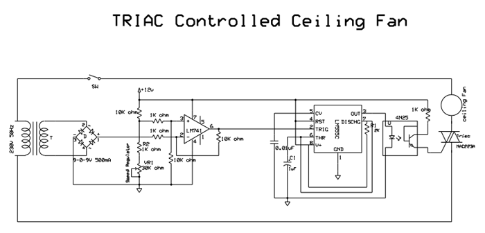
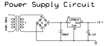
Conventional Ceiling fans operate with voltage divider circuit. Alternatively Ceiling fans can even be operated with Silicon Controlled Rectifiers TRIAC, and 555 timer circuits. This circuit is very cheap in its build. Circuit Diagram Tab 1 shows the TRIAC ceiling fan circuit while circuit diagram tab2 details with the power supply.
Working
The 230V 50Hz supply is first stepped down to 9V by the transformer and rectified by Bridge Rectifier. This is given to the pin2 (inverting input) of 741 op-amp. A Constant voltage obtained by adjusting the potentiometer of 30K ohm connected to 12V in voltage divider with 10K ohm is given to pin 3(non-inverting input) of op-amp 741. The op-amp is configured as difference amplifier with gain 10. The output of difference amplifier is given to trigger pin (pin 2) of 555 timer configured in monostable mode with pulse width of 2.2ms. When the stepped down rectified wave is below the voltage given at pin 3, the op-amp gives a high voltage, and when the voltage at pin2 exceeds the constant voltage given at pin 3, then output goes low, triggering the monostable multivibrator to give a pulse of constant duration of 2.2ms. In order to operate with 230V supply, optocoupler 4N25 is used to interface with TRIAC gate. This is to protect rest of the circuit coming in direct contact with 230V supply. The optocoupler makes the gate pin of TRIAC high for a small duration. This pulse fires the TRIAC and makes it conduct. This way pulse width of the ac wave across the fan can be modulated and speed of fan can be controlled. Switch SW can be used to turn on/off the fan.
Pulse width = 1.1 R1*C1 = 1.1 * 2K * 1uF = 2.2msec.
The bottom figure in the picture is the circuit for deriving 12 Volts supply.
Speed Regulator
As the potentiometer (Variable Resistor VR1 10K ohm) is adjusted the fan speed changes. Sliding potentiometer upwards increases the speed of fan.
For zero speed of fan, the potentiometer should be completely slided up, and the voltage at pin 3 will be 12*(31/31+10) = 9.073 V, the output of opamp is always high. For maximum speed of fan slide the potentiometer completely up. The voltage at pin 3 will be 12*(1/10+1) = 1.09 V. As potentiometer is slided up, the voltage at pin 3 comes down, and for every cycle opamp goes low within a short time and this triggers 555 timer, that fires the TRIAC. In conventional fans, fan speeds can be only at discrete levels as the regulator’s knob is rotated; this TRIAC controlled fan can vary speed of fan in continuous way.
The circuit uses no controllers, and different speeds of fan can be obtained as against the discrete speed levels of the currently existing ceiling fans.
Simulation
Simulation (with LT Spice)
Stepped down ac wave

Rectified sinusoidal waveform

Output of Difference Amplifier (for a particular position of potentiometer)

Output of Monostable Multivibrator

The 555 timer output is given to optocoupler’s LED, and the photodiode in the optocoupler conducts for a short duration and this fires the Triac. The firing angle determines the pulse width of sinusoidal wave across load.
The output across the fan is pulse width modulated sinusoid waves that control the speed of the ceiling fan.

Figure Output across the ceiling fan.
The shaded part of the sinusoid wave shown in the figure is the one that appears across the load (ceiling fan). This width changes as the resistance VR1 is varied, and fan speed changes.
Project Source Code
Circuit Diagrams
Filed Under: 555 Timers, Electronic Projects


Questions related to this article?
👉Ask and discuss on EDAboard.com and Electro-Tech-Online.com forums.
Tell Us What You Think!!
You must be logged in to post a comment.