What is UPS?
An uninterruptible power supply ,UPS or battery/flywheel backup, is an electrical apparatus that provides emergency power to a load when the input power source, typically mains power, fails. A UPS differs from an auxiliary or emergency power system or standby generator in that it will provide near-instantaneous protection from input power interruptions, by supplying energy stored in batteries or a flywheel. The on-battery runtime of most uninterruptible power sources is relatively short (only a few minutes) but sufficient to start a standby power source or properly shut down the protected equipment.
There are different types of UPS such as
1. On line UPS
2. OFF line UPS
3. Line interactive UPS.
What is Online UPS?
In an online UPS, the batteries are always connected to the inverter, so that no power transfer switches are necessary. When power loss occurs, the rectifier simply drops out of the circuit and the batteries keep the power steady and unchanged. When power is restored, the rectifier resumes carrying most of the load and begins charging the batteries, though the charging current may be limited to prevent the high-power Rectifier from overheating the batteries and boiling off the electrolyte.
The main advantage to the on-line UPS is its ability to provide an electrical firewall between the incoming utility power and sensitive electronic equipment.
What is Offline UPS?
In Off line UPS The protected equipment is normally connected directly to incoming utility power. When the incoming voltage falls below a predetermined level then UPS turns on its internal DC-AC inverter circuitry, which is powered from an internal storage battery. The SPS then mechanically switches the connected equipment on to its DC-AC inverter output. The switchover time can be as long as 10 milliseconds depending on the amount of time it takes the standby UPS to detect the lost utility voltage. The UPS will be designed to power certain equipment, such as a personal computer, without any objectionable dip or brownout to that device.
Off Line UPS the load is connected directly to the mains when main supply is available and it is not too high or not to low. When the over voltage or under voltage conditions are detected on the mains The UPS transfer the load to the inverter. When the line is present, the battery charges through the rectifier. Thus in Off-Line UPS There is a load Transfer involved every time the mains is interrupted and restored.
WLine interactive UPS:-
Line-interactive UPS. Typical protection time: 5–30 minutes. Capacity expansion: Several hours The line-interactive UPS is similar in operation to a standby UPS, but with the addition of a multi-tap variable-voltage autotransformer. This is a special type of transformer that can add or subtract powered coils of wire, thereby increasing or decreasing the magnetic field and the output voltage of the transformer. This is also known as a Buck–boost transformer.
Hardware Description
Hardware and Description:-
Block diagram of OFF line UPS:
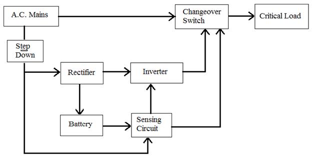
Off line UPS
1. AC mains
It is input to UPS system which is 230v with 50Hz constant frequency. This same supply is applied to load output when an AC main is present.
2. Step Down
Step Down transformer is used to step down input AC supply to 20V. in ups single transformer is used for step up and step down using multiple tab facility.
3. Rectifier
Bridge rectifier is used to convert step down AC voltage to pulsating DC.
4. Battery
It is main part of UPS system which decides the backup time of UPS battery selected using capacity of inverter and backup time require for System.
5. Sensing Circuit
In ups some feedback signals are nodded. sensing circuit is used to sense input mains supply and battery voltage o turn the inverter. It is build up with simple resistor divider circuit which provide voltage to comparator pin of PIC microcontroller.
6. Inverter
Normally in Single phase UPS Push-Pull configuration of inverter is used. Inverter converts input DC supply form battery into AC supply. Frequency of this inverter decide using switching pulses given by PIC microcontroller.
7. Change over switch
It contain DPDT relay which switches main AC supply and Inverter section when AC supply is on this relay is off and AC mains is connected to load and when AC supply is not available then DPDT relay is on and it gives inverter output to load.
Working
It is assumed that the reader has gone through the project How to get started with PIC and done all the things discussed in it.
1. Off line UPS DPDT relay operate as changeover switch. When AC supply is present this relay is off. When supply is absent or it is in under voltage range then this relay gets on. This switches mains supply and inverter supply to load output. This relay drives with transistor BC547 which is control via PIC microcontroller.
2. Incoming AC supply is step down and rectified using bridge rectifier to charge the battery of UPS. Output of bridge rectifier is given to LM317 which control charging voltage of battery. Power transistor TIP32 is used to boost input supply current to charge a battery. Current is boosted 5 times off the supply to charge the battery.
3. Initially PIC senses both input mains voltage and battery voltage if AC mains is available it off DPDT relay .
4. If AC mains is off then PIC microcontroller on DPDT relay which change output to inverter section.
5. In mains off condition PIC microcontroller also provide pulses to inverter section which generate 50Hz output at inverter section.
6. Inverter gets on only when battery voltage is sufficient to give required output otherwise inverter is off.
Component List:-
Transformer 0-16 V (1 Amp), 2.5 Amp. Step up transformer, DPDT Relay, Diode Bridge 2 Amp., Resistor, Capacitor, MOSFET IRFZ 44, LM317T, TIP 32, IC MCT6, BC548, Diode 1N5408, PIC 16F684, battery 12V(7.5Ah)
TEST & Results
Output voltage:
Mains on: 230+/-5% Volts
UPS on: 230+/0.5%Volts
Output Voltage waveform:- Square.
Output frequency:
Mains on : 50Hz +/3%
UPS on: 50Hz+/-1Hz
Output power Wattage 460 watt.
Maximum current 2.5A.
Input voltage (Battery voltage): 12V/7.5AH
Design Calculations
Design Calculations:
Battery Charger and Power supply section:
The charger is designed to charge 12 V, 7.5 AH sealed lead acid battery. It consists of step down transformer to step down mains supply to 16 V. And the regulator section LM 317T, current booster TIP 32, LM 7806 to supply the PIC 16F684, and to inverter driver.
The transformer voltage is 0-16 Volt hence, the D.C. Voltage is
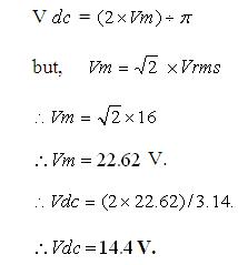
The regulator LM317T which is used is having capacity of 1.5 Amp current, but regarding to the load (battery) current requirement the external current booster (TIP 32) transistor is used to boost the current up to 5 Amp.
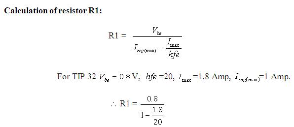
R1 = 0.8719Ohm ~ 1 Ohm
Calculation for wattage of transformer
P=V*I*POWER FACTORE
P=230 v * 2.5A* 80%
P = 460 Watts
Calculation for voltage sensing circuit
V0= R2/ (R1+R2)* Vin
4V== R2/ (R1+R2)* 12
R2 = 1K, R1 = 2K
Maximum Current to the microcontroller must be less than sinking current of microcontroller, here current to microcontroller calculated as
V=IR
I=4 v/ 1K = 4 ma
To limit this excessive current additional 440 ohms register is used and the actual current less than sinking current of microcontroller which as 15 mA.
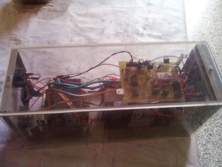
Circuit Images
Circuit Images

Project Source Code
###
/*----------------------------------------------------------------------------------------*/
/*Program for Single Phase OFF-LINE UPS.*//*-------------------------------------------------------------------------------------------*/#include<htc.h>__CONFIG(0X3Fd5); // Configure PIC#define _XTAL_FREQ 4000000unsigned int c;/*--------------------------------------------------------------------------------------------------*/init(){OSCCON = 0b01100001; // oscillator to generate 4 Mhz.OSCTUNE = 0X07; // Tune oscillator to 4 Mhz.T1CON = 0x00;TMR1H = 0xee; // load timer high count.TMR1L = 0x68; // load timer low count.TMR1IE = 0; //Enable timer interrupt.TMR1IF = 0; //clear timer flag.CMCON0 = 0X05; //Enable comparator.TRISA = 0X00; // PORTA as output.ANSEL = 0X00; //Analog channels are shut off.TRISC = 0X03; // PORTC pin 0 and 1 are as input.INTCON = 0XC0; // Global and peripheral interrupt enable.C2IE = 1; //Comparator interrupt enable.C2IF = 0; //comparator flag disable.C2INV = 0; //Comparator non inverted.return;}/*------------------------------------------------------------------------------------------*/blink(void){RC4 = 0; //function to blink the ledif(c==2){RC4 = 1;__delay_ms(200);RC4 = 0;__delay_ms(200);}return;}/*--------------------------------------------------------------------------------------------------*/ unsigned short int b;void main(){init();__delay_ms(50);while(1){blink();}}/*----------------------------------------------------------------------------------*/interrupt isr(){static unsigned short a=0;if(C2IF & C2IE){C2IF = 0; //Clear comparator flag.if(C2OUT==0) //Comparator falling interrupt.{TMR1IE = 1; //Timer interrupt enable.RC5 = 0;RA0 = 0;TMR1H = 0xee; //Load timer count.TMR1L = 0x68;TMR1ON = 1; //Set timer onc=2;}if(C2OUT==1) //Comparator rising interrupt{RC2 = 0;RC3 = 0;RC4 = 0;RC5 = 1;RA0 = 1;TMR1IE = 0;TMR1ON = 0;c=0;}}if(TMR1IE & TMR1IF) // GENERATION OF THE PWM FOR INVERETR{TMR1IF = 0;TMR1ON = 0;a++;RC2 = 0;RC3 = 0;__delay_us(100);if(a%2==0){RC2 = 1;RC3 = 0;b = 2;}if(a%2!=0){RC2 = 0;RC3 = 1;b = 1;}TMR1H = 0xee; //Reload timer count.TMR1L = 0x68;TMR1ON = 1;b = a;}}
###
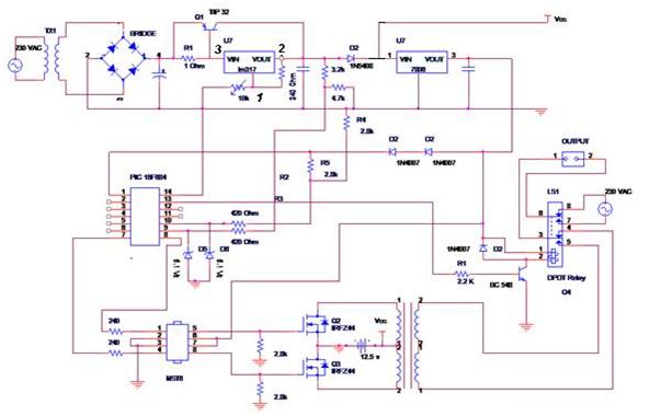
Circuit Diagrams
Filed Under: Electronic Projects

Questions related to this article?
👉Ask and discuss on EDAboard.com and Electro-Tech-Online.com forums.
Tell Us What You Think!!
You must be logged in to post a comment.