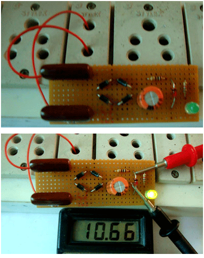
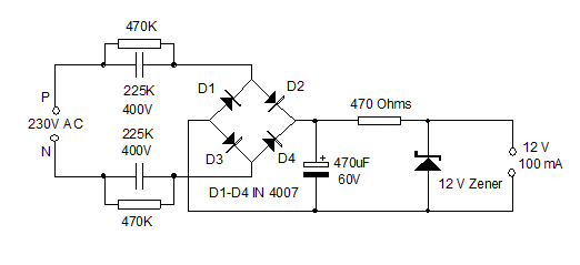
This capacitor power supply can deliver 12 volt DC and 100 mA current to power low current devices. It is provided with surge protection and is totally isolated from mains supply using two capacitors in the phase and neutral lines. So the connected device is safe even if the phase and neutral lines changes.
Transformer less power supply is used to reduce size and cost of electronic gadgets. Only low current devices can be run in transformer less power supply, since the output current is low. Unlike resistive type power supply, capacitive power supply isolates mains from the circuit and drops mains to low volt AC without generating heat. So power loss due to heat generation is negligible. The power supply works safely unless the capacitor burn out due to very high surge current. Costly equipments should not be connected to capacitive power supply.
Do not use this power supply for testing prototypes or as battery charger.
Do not construct this on Bread board. Use common PCB.
Circuit description
1. A 250 Volt MOV is connected across the phase and neutral as surge protector.
2. Capacitors C1 and C2 are in series with the phase and neutral lines to drop AC. C1 and C2 are 225 J 600 volt AC capacitors which drops 230 volt AC to low volt AC through the capacitive reactance property. Output voltage from the capacitor slightly varies depending on the input AC voltage. Output current is around 100 -120 mA. The output current depends on many factors such as the quality of material used in the capacitor, input AC voltage etc. So precision in voltage and current will not be available in capacitor power supply. As a rule each 1 uF can give 80-100 mA current.
3. R1 and R2 are bleeder resistors to remove the stored current from C1 and C2 at power off. These capacitors can store more than 400 volts which should be removed to avoid shock using the bleeder resistor.
4. D1 through D4 forms a full wave bridge rectifier to convert AC to DC. IN 4007 diodes can handle up to 1 amp current.
5. C3 is the smoothing capacitor to remove ripples from the rectified voltage. As a rule, the voltage rating of the smoothing capacitor should be three times higher than that of the rectified voltage. Here 60 volt capacitor is used. Smoothing of DC depends on the value of the capacitor. A standard value is 470 uF. But clean ripple free DC will be available if the value increases to 1000 or 2200 uF.
6. Resistor R3 is the current limiter for the Zener diode ZD.
7. ZD is the 12 volt 1 watt Zener diode to regulate the output voltage to 12 volt DC. Zener diode requires more than 2 volts excess than its rated voltage for quick breakdown.
8. LED indicates the output current. If LED is used at the output, there will be some voltage drop (around 1.6-1.8 volts) at the output. If 12 volt is needed, omit LED.

Fig. 1: Image of Capacitor Power Supply
Note: 1.4 volts drop is due to LED
Circuit Diagrams
Filed Under: Circuit Design


Questions related to this article?
👉Ask and discuss on EDAboard.com and Electro-Tech-Online.com forums.
Tell Us What You Think!!
You must be logged in to post a comment.