Engineers Garage

  • Projects and Tutorials
    • Electronic Projects
      • 8051
      • Arduino
      • ARM
      • AVR
      • PIC
      • Raspberry pi
      • STM32
    • Tutorials
    • Circuit Design
    • Project Videos
    • Components
  • Articles
    • Tech Articles
    • Insight
    • Invention Stories
    • How to
    • What Is
  • News
    • Electronic Products News
    • DIY Reviews
    • Guest Post
  • Forums
    • EDABoard.com
    • Electro-Tech-Online
    • EG Forum Archive
  • Digi-Key Store
    • Cables, Wires
    • Connectors, Interconnect
    • Discrete
    • Electromechanical
    • Embedded Computers
    • Enclosures, Hardware, Office
    • Integrated Circuits (ICs)
    • Isolators
    • LED/Optoelectronics
    • Passive
    • Power, Circuit Protection
    • Programmers
    • RF, Wireless
    • Semiconductors
    • Sensors, Transducers
    • Test Products
    • Tools
  • EE Resources
    • DesignFast
    • LEAP Awards
    • Oscilloscope Product Finder
    • White Papers
    • Webinars
  • EE Learning Center
    • Design Guides
      • WiFi & the IOT Design Guide
      • Microcontrollers Design Guide
      • State of the Art Inductors Design Guide
  • Women in Engineering

Smart Home Automation using AVR

By Ashok Sharma


In this technological world, automatic systems are being preferred over manual system. In this series Home Automation plays an important role for humans. In this unit we talk about basic needs to understand the project well and also for its future advancements.

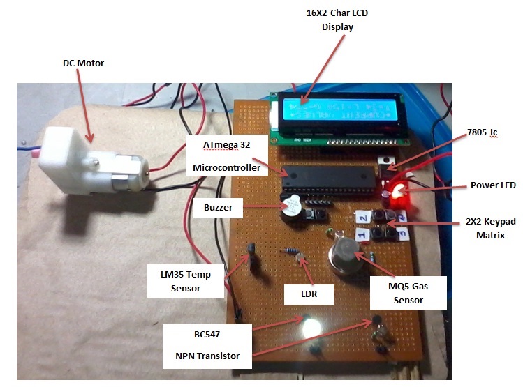
We are going to talk about different types of sensors (i.e. Temperature Sensor, LPG Gas Sensor, LDR) and input and output devices (i.e. 2×2 matrix Keypad, Buzzer, DC Motor, 16×2 Char LCD Display, Power Supply section etc.). Now we are going to Interface all those with the brain of the system ‘Microcontroller (i.e. ATmega16/16L)’ and let’s find out what the individual role of each component are and how they act as Smart Home System together. For this project Reader should have knowledge about How to start with AVR and Interface LCD with AVR .

BLOCK DIAGRAM

Smart Home Automation

BLOCK DIAGRAM DESCRIPTION

MQ-5 LPG SENSOR

It senses the leakage of LPG. The out put of this sensor is ‘high’ at normal condition. The output goes low, when it senses the LPG.

AVR (ATmega16/16L- 8 bit) MICROCONTROLLER

It is the whole control of the project. It controls the DC Motor, Buzzer and when LPG leak occurs, Temperature increases etc. The input/ output ports of the microcontroller is used for this.

LDR

LDR is used to check Sun light intensity; so that we can know it is Day or Night.

LM35 Temp Sensor

It is used to measure room temperature and give it to microcontroller for desirable action.

16×2 Char LCD Display

It is used to display all sensors’ value and action taken by system on display.

2×2 Matrix Keypad

It is used for enter password to access the door.

DC Motor

It is used for opening and closing the door.

 Working Principle and Circuit

WORKING PRINCIPLE

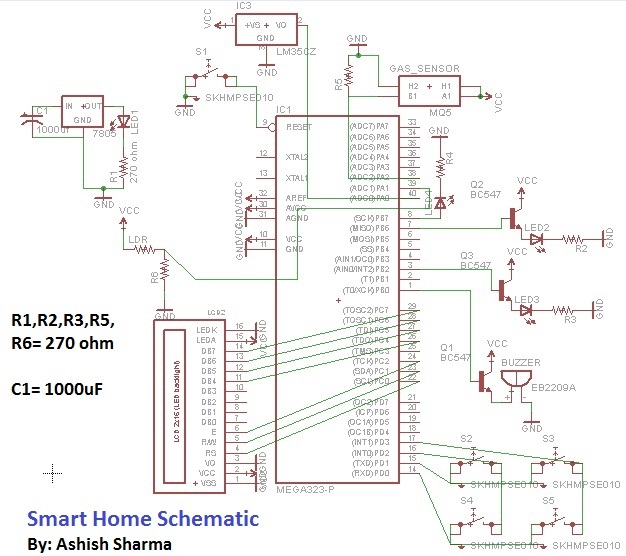
In this project I used three analog sensors i.e. Temp, LPG Gas and LDR. These are given analog output. So as per interfacing required, I connected all the analog output of the sensors to in-build ADC to get digital values and keypad, DC Motor, LCD Display, buzzer, transistors and LED to i/o pins of the microcontroller. For connections, please refer schematic diagram as given below.

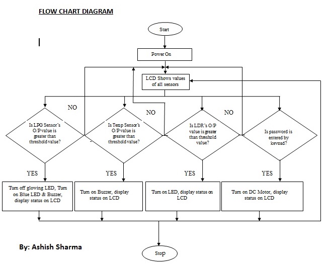
Now when power on, first Red LED indicates the power status of the system and if it is then all peripherals are initialized and their current value will be displayed on LCD after welcome message ‘WELCOME TO SMART HOME’. Now every sensor has their threshold value according to ADC conversion mentioned in C Source Code according to the requirements and all o/p device are controlled by microcontroller based on sensors output and act accordingly. We can change those threshold values according to our need by changing in C Source code any time.

For better understanding, let’s take the example of Temp sensor. After ADC process, in my project I assign 50*C as a threshold for temp sensor. So when the temp sensor’s ADC value rises more than its threshold value that point of time microcontroller gives signal to buzzer for beeping and LCD to display ‘Temp Increased’ and if value is under the threshold value, then everything is normal. So like this, every sensor has its threshold value and microcontroller always compare the current ADC value with threshold value and if it exceeded, desirable action takes place by the microcontroller.

I have also interfaced to NPN (BC547) transistor for relay to operate. If I want to switch ON/OFF any AC device according to Temp Sensor or LDR, I can connect relay to transistor to operate.

This home automation project has three different LED with different colour. First is Red colour LED, which indicates about power supply in the system. Second is Blue colour, which indicates the LPG Gas leakage and third is White colour which indicates the ON/OFF state of transistors.

I have also interfaced a 2×2 Matrix keypad which is used to type password to open the door.

In my code, ‘123’ is the password to open the door. When you pressed ‘123’ by keypad shown in diagram and a ‘enter’ button is also there with ‘enter’ signed. When you pressed ‘enter’ button, your current password is compared with password written in C source code. If it is right, then DC motor rotates and door will be open, if wrong then a short beep by buzzer and a message ‘Wrong Pass’ will be displayed on LCD. Now you have to try again.

So in this way every component and circuit has its individual role which is continuous monitored by microcontroller. 

MICROCONTROLLER CIRCUIT WITH PHERIPHERALS
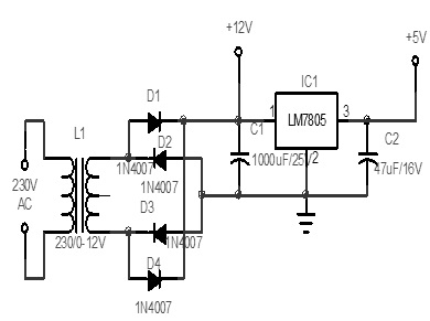
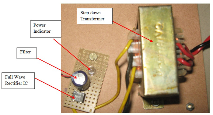
Smart Home Automation


POWER SUPPLY

Power supply for the complete unit can be derived from the mains using a step-down transformer of 230V AC primary to 0-12V, 500mA secondary. A full- wave rectifier followed by a capacitor filter is the output voltage and feeds it to the 5-volt regulator (LM7805) whose output is used to the power supply requirements of microcontroller circuit, other IC’s.

Power Supply Circuit Diagram


Power Supply DIY


FLOWCHART


AVR Project

CONCLUSION

An automated home can be easily implemented with the grouping of simple controls or it can be more compelled if we are going to use electrical appliances or remote controlled electrical appliances. A compelled system cost more than this in different parameters.

Well more knowledge is gained and more experiences are faced. Lot of information’s are collected ultimately, I have concluded with a great pleasure for achieving our aim.

 I have planned to fulfill my technical requirements. The knowledge I have attained with this project really would follow till the end of my career.


Circuit Diagrams

Smart-home-Schematic


Filed Under: Electronic Projects
Tagged With: avr, home automation
 

Questions related to this article?
👉Ask and discuss on EDAboard.com and Electro-Tech-Online.com forums.


Tell Us What You Think!! Cancel reply

You must be logged in to post a comment.

HAVE A QUESTION?

Have a technical question about an article or other engineering questions? Check out our engineering forums EDABoard.com and Electro-Tech-Online.com where you can get those questions asked and answered by your peers!


Featured Tutorials

  • PS2 Keyboard To Store Text In SD Card Using Arduino Circuit Setup On Breadboard
    How To Use PS2 Keyboard To Store Text In SD Card Using Arduino- (Part 42/49)
  • Wireless Path Tracking System Using Mouse, XBee And Arduino Circuit Setup On Breadboard
    How To Make A Wireless Path Tracking System Using Mouse, XBee And Arduino- (Part 43/49)
  • How to Make a Wireless Keyboard Using Xbee with Arduino- (Part 44/49)
  • Making Phone Call From GSM Module Using Arduino Circuit Setup On Breadboard
    How to Make Phonecall From GSM Module Using Arduino- (Part 45/49)
  • How to Make a Call using Keyboard, GSM Module and Arduino
    How To Make A Call Using Keyboard, GSM Module And Arduino- (Part 46/49)
  • Receiving SMS Using GSM Module With Arduino Prototype
    How to Receive SMS Using GSM Module with Arduino- (Part 47/49)

Stay Up To Date

Newsletter Signup

Sign up and receive our weekly newsletter for latest Tech articles, Electronics Projects, Tutorial series and other insightful tech content.

EE Training Center Classrooms

EE Classrooms

Recent Articles

  • Renesas delivers intelligent sensor solutions for IoT applications
  • Microchip Technology releases AVR-IoT Cellular Mini Development Board
  • Qualcomm acquires Cellwize to accelerate 5G adoption and spur infrastructure innovation
  • MediaTek’s chipset offers high-performance option for 5G smartphones
  • Nexperia’s new level translators support legacy and future mobile SIM cards

Most Popular

5G 555 timer circuit 8051 ai Arduino atmega16 automotive avr bluetooth dc motor display Electronic Part Electronic Parts Fujitsu ic infineontechnologies integratedcircuit Intel IoT ir lcd led maximintegratedproducts microchip microchiptechnology Microchip Technology microcontroller microcontrollers mosfet motor powermanagement Raspberry Pi remote renesaselectronics renesaselectronicscorporation Research samsung semiconductor sensor software STMicroelectronics switch Technology vishayintertechnology wireless

RSS EDABOARD.com Discussions

  • Bursts in AHB lite
  • Thermal pad
  • lna+mixer noise figure problem
  • ADS Cascode Power Amplifier Loadpull Problem
  • SMPS topology

RSS Electro-Tech-Online.com Discussions

  • Voltage integration in LTspice (net volts across inductor)
  • Where is the fuse ?
  • 500+V power supply from 9V battery using ZVS
  • Control Bare LCD With ATmega328p
  • undefined reference header file in proteus
Engineers Garage
  • Analog IC TIps
  • Connector Tips
  • DesignFast
  • EDABoard Forums
  • EE World Online
  • Electro-Tech-Online Forums
  • Microcontroller Tips
  • Power Electronic Tips
  • Sensor Tips
  • Test and Measurement Tips
  • 5G Technology World
  • About Us
  • Contact Us
  • Advertise

Copyright © 2022 WTWH Media LLC. All Rights Reserved. The material on this site may not be reproduced, distributed, transmitted, cached or otherwise used, except with the prior written permission of WTWH Media
Privacy Policy | Advertising | About Us

Search Engineers Garage

  • Projects and Tutorials
    • Electronic Projects
      • 8051
      • Arduino
      • ARM
      • AVR
      • PIC
      • Raspberry pi
      • STM32
    • Tutorials
    • Circuit Design
    • Project Videos
    • Components
  • Articles
    • Tech Articles
    • Insight
    • Invention Stories
    • How to
    • What Is
  • News
    • Electronic Products News
    • DIY Reviews
    • Guest Post
  • Forums
    • EDABoard.com
    • Electro-Tech-Online
    • EG Forum Archive
  • Digi-Key Store
    • Cables, Wires
    • Connectors, Interconnect
    • Discrete
    • Electromechanical
    • Embedded Computers
    • Enclosures, Hardware, Office
    • Integrated Circuits (ICs)
    • Isolators
    • LED/Optoelectronics
    • Passive
    • Power, Circuit Protection
    • Programmers
    • RF, Wireless
    • Semiconductors
    • Sensors, Transducers
    • Test Products
    • Tools
  • EE Resources
    • DesignFast
    • LEAP Awards
    • Oscilloscope Product Finder
    • White Papers
    • Webinars
  • EE Learning Center
    • Design Guides
      • WiFi & the IOT Design Guide
      • Microcontrollers Design Guide
      • State of the Art Inductors Design Guide
  • Women in Engineering