Huge amount of energy is wasted as the street lights are kept on throughout the evening and for the entire night. Other LDR based street lights are automatically lit up in darkness. But this project is totally different in a way that its energy efficient circuit senses a vehicle on the lane or road. It is an innovation of street lights to a greater level. It also counts the number of vehicles which can be used to analyze how much amount of energy is being saved.
Circuit Description
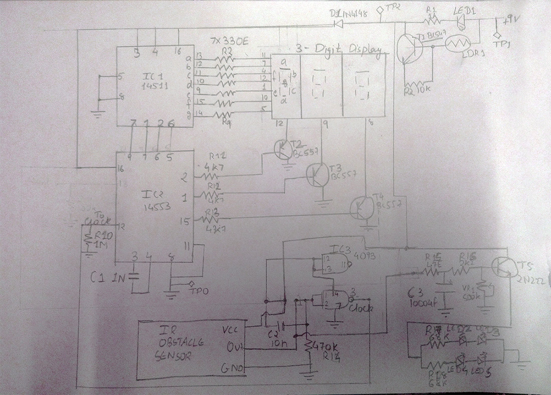
The circuit is built around the popular ICs (IC1 and IC2), Light Dependent Resistor (LDR1), transistors BC547 (T1), BC557 (T2, T3, T4), 3-Digit Display. The resistance of LDR1 decreases when the intensity of light falling on it increases and vice versa. In darkness or during the absence of light, the LDR exhibits a resistance in the range of mega-ohms, which decreases to a few hundred ohms in the presence of bright light.
Here, the amount of light falling on LDR1 decreases with the darkness. Consequently, the resistance of LDR1 increases to provide a clock pulse and 6v-9v is passed. During this time, LED1 stops glowing.
The 14553 is a 3-digit BCD (Binary Coded Decimal) counter. Inside the chip, each counter drives a 4-bit latch with quad 3-input multiplexer. The chip carries Reset, an input clock and Latch Enable functions. The 1nf myler capacitor on pins 3 and 4 sets the multiplex scan rate to about 1 kHz.
The four outputs (QotoQ3) are fed into the 14511 cmos 7-segment decoder driver. The outputs of this driver then go to the 3-digit multiplexed display unit. Each digit is turned at the correct time via the display control outputs at pins 2, 1 and 15 of the 14553. These are active low outputs each driving a BC 557 NPN transistor via a 4k7 resistor. The transistor in turn switches the common cathode of the digits in the display.
The counter module is a typical debounce circuit. The resistance and capacitor provide a delay period during which as the switch establishes connection through it, the obstacle sensor will register a count.
The R15 protects the capacitor from over-current shock, when the vehicle is passed, R15 and R16 will determine the time that the transistor will supply current to the LEDs, as they actually determine the discharge of the capacitor.
The R15 protects the capacitor from over-current shock, when the vehicle is passed, R15 and VR1 will determine the time that the transistor will supply current to the LEDs, as they actually determine the discharge of the capacitor.
*(didn’t get the meaning, repetitive)
To adjust the off-delay time, play with the R3 potentiometer. Higher resistance means more time to turn the LEDs off. You can further increase the off-delay time, by changing the C1 capacitor. For example, a 220uF or a 470 uF,or bigger. The more the capacitance, the more is the off-delay.
With 9V power supply, each row can have 2 LEDs. The limiting resistor for each row is 68 Ohms, and a current of 24 mA is drawn.
As a result when vehicle is sensed, street lights glows till the vehicle is present in the range of street light.
Limitation
· This schematic applies to LEDs with operation current 30 mA and voltage drop 3.6 Volts.
· The image shows how to place street lights.
http://www.engineersgarage.com/contribution/smart-street-lights-system

Fig. 1: Overview of Automatic Street Lights
Circuit Diagrams
Filed Under: Electronic Projects


Questions related to this article?
👉Ask and discuss on EDAboard.com and Electro-Tech-Online.com forums.
Tell Us What You Think!!
You must be logged in to post a comment.